1. HOW TO INSTALL THE UNIT
13
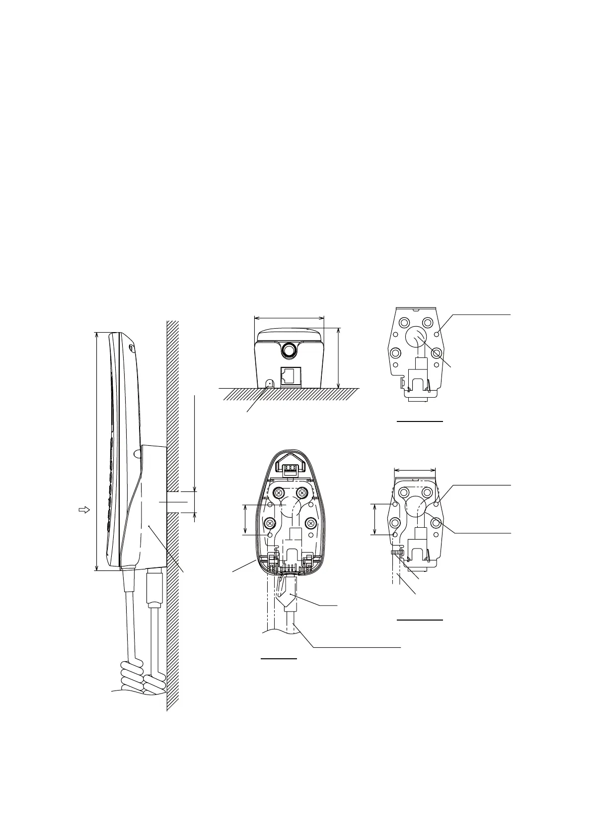
1.3 IP Handset
The IP handset functions as a display and it may also be used for normal voice communication.
The units (max 26 units) may be installed anywhere onboard the vessel. The IP handset is pro-
vided with a cradle. Fix the cradle to the bulkhead or installation panel. The cradle has two cable
entries for convenience; bottom and rear.
1. To use the rear cable entry, make a hole of 18 mm (0.71") diameter in the installation site,
Refer to the outline drawing.
2. Remove four screws from the cradle to separate the plastic case from the metal plate.
3. Fix the metal plate to the mounting site with four self-tapping screws.
4. Connect the LAN cable from the CU to the inner RJ45 port in the cradle.
5. If the bottom cable entry is used, run the LAN cable as shown in the figure below and fix it with
a cable-tie.
6. Reattach the plastic cover.
7. Connect the cable from the handset to the outer RJ-45 port of the cradle.
59 (2.32")
204 (8.03")
26 (1.02")
RJ45
52 (2.05”)
VIEW A
Cable entry
(bottom)
CRADLE
Cable entry (rear entry)
Cable from the handset
26 (1.02")
4-
φ
4
Fixing holes
φ
18 (0.71")
Cable entry
(rear )
35±0.5 (1.38")
Cable from the CU
Fix with a cable-tie
Metal plate
(Bottom)
Metal plate
(Rear)
4-
φ
4
Fixing holes
Cable entry
from the CU
 Loading...