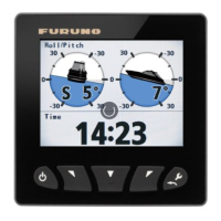
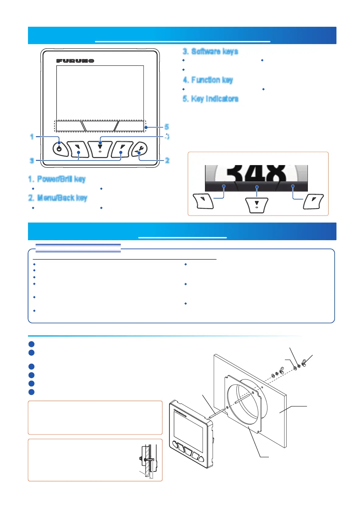
UNIT OVERVIEW, FUNCTIONS
INSTALLATION
Turn power on/off Open Brilliance window
Change displayed page
Confirm selection/changes Switch displayed data
Adjust settings
Move cursor
Open/close the menu Go back one menu layer
The indicators show the operative function for the
Software and Function keys. Press any key to display
the indicators. If there is no operation, the indicators are
minimized after a short period of time, however, they are
always displayed when a menu is open. The indications
vary, depending on the displayed screen/menu.
Installation considerations
When installing the FI-70, keep the following points in consideration:
Select a well-ventilated location.
Select a location with minimal vibrations and shock.
Keep the FI-70 away from heat sources.
Observe the compass safe distances.
(Standard: 0.30 m, Steering: 0.30 m)
Select a location with a smooth surface.
(1 mm flatness or less)
Keep cable lengths in mind when selecting the
mounting location.
When not in use, fit the rubber cover to the FI-70.
Leave sufficient room surrounding the FI-70 to allow
fitting of the rubber cover.
Referring to the outline drawings at the back of the
handbook, leave sufficient space for service and
maintenance.
Where the rear connector or T-connectors may get
wet, waterproof the connectors. (See page 4 for how
to waterproof the connectors.)
Flushmount Installation
Using the supplied template, mark and cut a hole in the installation location.
Fit the supplied stud bolts (M3×40, 2 pcs) to the rear of the FI-70.
Note:
Do not use tools to fit or insert the stud bolts.
Fit the supplied flushmount sponge to the rear of the FI-70.
Set the FI-70 into the mounting hole.
Fit and tighten the washers and butterfly nut.
1
2
3
5
Referring to page 4, connect and ground the FI-70.
4
6
Spring washer
Butterfly
nut
Flat washer
Console
Flushmount sponge
Stud bolt
When retrofitting from the FI-50 series unit to the FI-70,
drill new bolt holes to fit the stud bolts for the FI-70. The
FI-70 can then be installed in place of the FI-50 series unit.
Using locally supplied materialsUsing locally supplied materialsUsing locally supplied materialsUsing locally supplied materialsUsing locally supplied materials
When using locally supplied screws to
secure the FI-70, the thread depth
should be approx. 5 mm, as indicated
in the figure to the right.
Approx.
5 mm
 Loading...