5. INSTALLATION AND INITIAL SETTINGS
5-5
5.2 Wiring
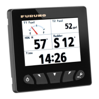
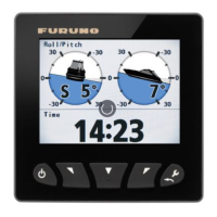
The FI-70 is able to display information from various sensors. The typical configuration
example shown in "SYSTEM CONFIGURATION" on page vi uses the optional data
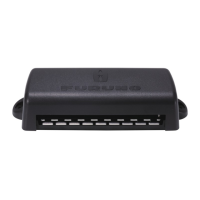
converter (IF-NMEAFI) to show information from the analog sensors. The FI-70 is part
of a network, connected via a CAN bus/NMEA2000 backbone.
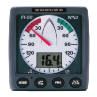
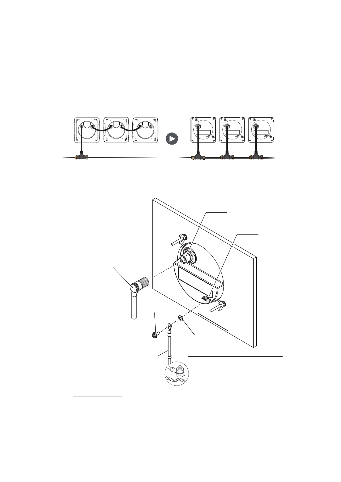
Note: Unlike the FI-50 series, the FI-70 can not be daisy-chained. When retrofitting
from the FI-50 series, connect each FI-70 to the CAN bus (NMEA2000) backbone.
5.2.1 How to connect the unit
NMEA2000 port
Using the supplied cable assembly, connect the FI-70 to the CAN bus/NMEA2000
network backbone. The FI-70 must be on the same network as the sensors you wish
to connect to. Power is also supplied via the CAN bus/NMEA2000 backbone to the
FI-70.
Before retrofitting
FI-50 series
FI-70
After retrofitting
CAN bus (NMEA2000) backbone CAN bus (NMEA2000) backbone
NMEA2000 port
Ground
terminal
Console rear
Cable assy.
(FI-70-0600, 6 m)
To CAN bus/NMEA2000
network backbone
Flat washer*
Ship’s ground terminal
Ground wire
(IV-1.25sq., local supply)
Terminal
screw*
*: Attached to FI-70, remove to install
 Loading...