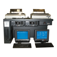
3. RC18xx Console Wiring
3-2
3.1 Electrical Connections (Continued)
Refer to RC1815/RC1825 and RC1840 Meter Box Assembly Drawing
3.1.5 PR-850A Power Supply
Determine the AC Input to be used with the PR-850A (Factory setting is for
220 VAC). Using the diagram supplied with the PR-850A, open the supply and set
the transformer taps for the correct voltage. Reassemble the supply.
PR-850A => Console and Outside Connections
PR-850A Front Connections
1) AC IN => AC Input from Ships Mains (100 to 240 VAC)
2) 24 VDC Output => Not Used
PR-850A Rear Connections (RC1815 and RC1825)
1) Battery IN (Negative) = > TB1-5 Meter Box Assembly
2) Battery IN (Positive) = > TB1-6 Meter Box Assembly
3) AC Fail (Positive) => TB1-7 Meter Box Assembly
4) AC Fail (Negative) = > TB1-8 Meter Box Assembly
5) 24 VDC OUT (Negative) = > TB1-9 Meter Box Assembly
=> TB2 FS-1570/ FS-2570 Transceiver
6) 24 VDC OUT (Positive) => TB1-10 Meter Box Assembly
=> TB1 FS-1570/ FS-2570 Transceiver
PR-850A when used with the RC1840
24 VDC OUT (Neg. and Pos.) => To FS-5000 Transceiver.
* The FS-5000 requires 60 Amps peak current.*
3.1.6 NMEA/IEC-61162 Connections
Refer to Pg. S-6, Felcom 15, IC-315 Junction Box Connections drawing.
 Loading...