41
6. CATCH SENSOR OPERATION
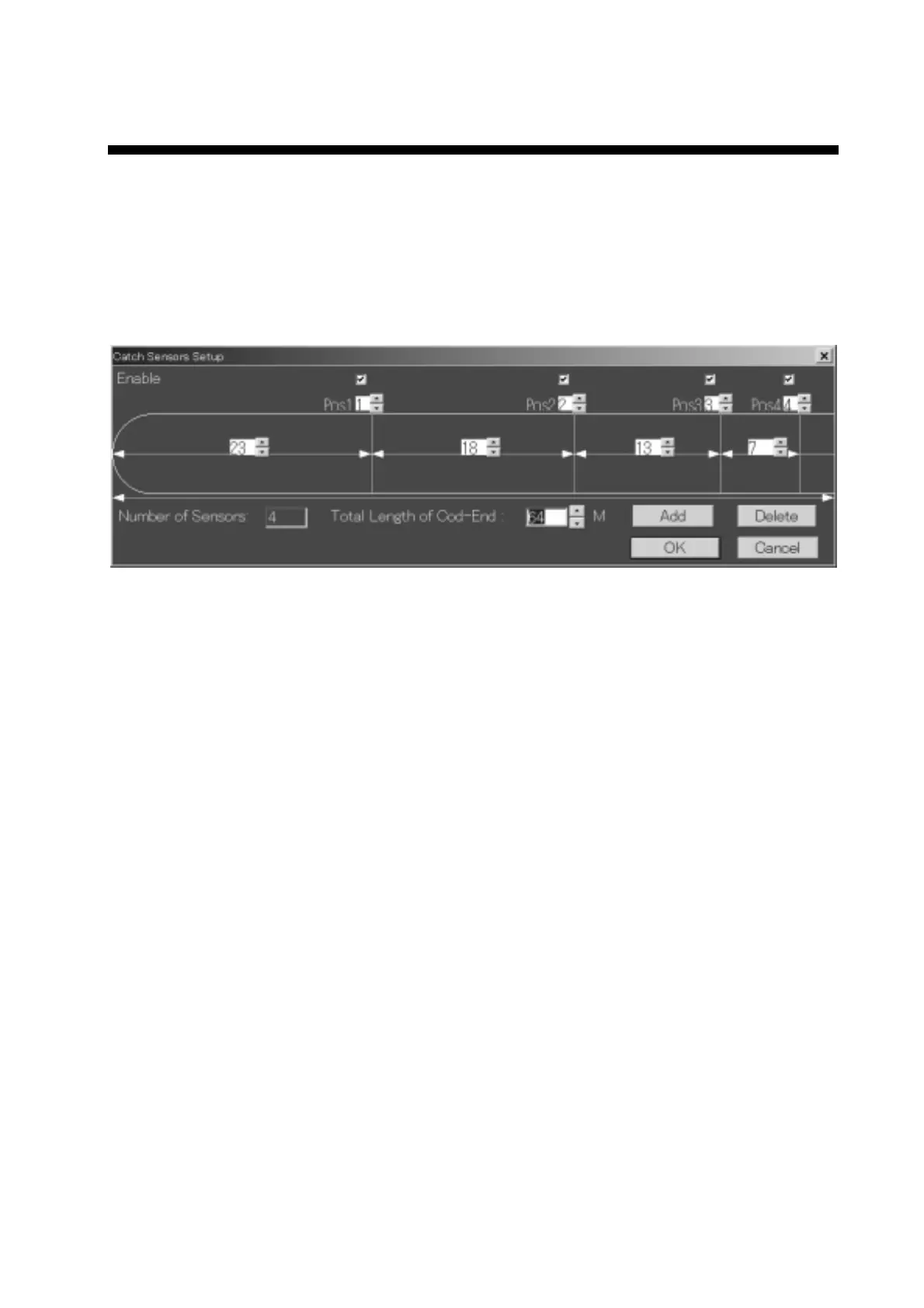
6.1 Catch Sensor Dialog Box
The Catch Sensor Setup dialog box provides a tool for you to configure the
catch sensors on a trawl net. You can install up to four catch sensors on the
TS-331A system. TS-331A program default settings display four catch sensors.
You can click the Delete button in this dialog box to remove catch
sensor/sensors if less than 4 catch sensors are installed.
Catch sensor setup dialog box
The Catch Sensor Setup dialog box provides the following options:
Enable catch sensor (check boxes)
Checking/Unchecking the “Enable Catch Sensor” check box will enable/disable
that particular catch sensor. There can be a maximum of four catch sensors
installed at a time.
Catch Sensor ID (edit boxes)
The Catch Sensor ID is a number used to distinguish different catch sensors.
Each sensor transmits an acoustic signal with its own fixed frequencies so the
system knows which one is installed (received a standby signal) or triggered
(received a triggered signal). TS-331A uses number 1 to 4 to distinguish them.
1: 69.75kHz/70.25kHz ±50Hz
2: 72.25kHz/72.75kHz ±50Hz
3: 74.75kHz/75.25kHz ±50Hz
4: 77.25kHz/77.75kHz ±50Hz
It is not required to install the sensor number 1 at the first position (Pos1), sensor
number 2 at the Pos2, etc. You may install sensor number 1 at Pos4, for
example. In this case, you need to input the right numbers of the sensor ID at
the corresponding position.
 Loading...