26
ڀ ŪŲŃƗƒŃŷŤťůŨŃŲũŃŦŲűŷŨűŷŶ
R7208SBCHModetable
Output
connector
Channel
Mode A
Mode B
Mode C
Mode D
Mode E
Mode F
Mode G
Mode
H
Mode
I
Mode
J
1 1111999
17 17 17
2 2 2 2 2 10 10 10
18 18 18
3 3 3 3 3 11 11 11
19 19 19
SB2 / 4
444
S.BUS2
12 12 12
20 20 20
SB2 / 5
555
S.BUS2
13 13 13
21 21 21
SB2 / 6
666
S.BUS2
14 14 14
22 22 22
SB2 / 7
77
S.BUS2
S.BUS2
15 15
S.BUS2
23 23
S.BUS2
SB / 8
8
S.BUS
S.BUS
S.BUS
16
S.BUS
S.BUS
24
S.BUS
S.BUS
LED
blink
RED 1
RED 2
RED 3
RED 4
RED 5
GREEN 1
GREEN 2
GREEN 3
GREEN 4
GREEN 5
Default
1
Turnonthereceiver. [TransmitterisalwaysOFF]
2
PressandholdtheSWfor5secondsto10seconds.
3
WhentheLEDofthereceiverchangesfromblinking
redtoblinkingorange,SWisreleased.
4
TheLEDshouldnowblinkredtwotimesinthe
patternsdescribedinthechartbelow.
5
EachpressoftheSWadvancesthereceivertothe
nextmode.
6
Whenyoureachthemodethatyouwishtooperate
in,pressandholdtheSWformorethan2seconds.
WhenLEDblinksinorange,itisthecompletionofa
modechange,SWisreleased.
7
Cyclethereceiverpoweroffandbackonagainafter
changingtheChannelmode.
1
Turnonthereceiver. [Transmitteris
alwaysOFF]
2
Receiverenterslinkwaitingstate
3
TheLEDwillflashforthecurrentCH
outputmode.
LINK LED
Red Solid
Start → 2second
later → Red Blink
(3 second)
Current CH mode
display
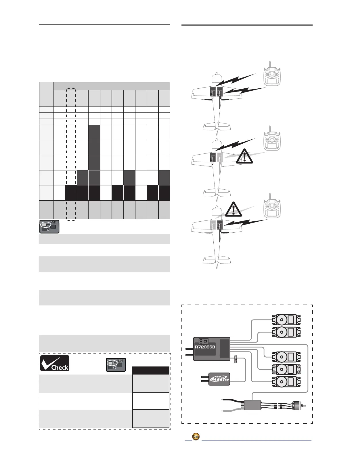
ChannelModes
7KH56%LVFDSDEOHRIFKDQJLQJLWVFKDQQHO
DOORFDWLRQVDVGHVFULEHGLQWKHWDEOHEHORZ7KLVLV
HVSHFLDOO\LPSRUWDQWZKHQXVLQJWKHUHFHLYHULQDGXDO
UHFHLYHUPRGH6HH\RXUWUDQVPLWWHURSHUDWLRQPDQXDO
IRUFRPSOHWHGHWDLOVRQRSHUDWLQJLQWKHGXDOUHFHLYHU
mode.
Communicate with two receivers
Receiver : A Receiver : B
Even if there is a problem with
the B receiver, communication
will be performed with the A
receiver.
Even if there is a problem with
the A receiver, communication
will be performed with the B
receiver.
,Q'XDO5;OLQNPRGHWKH6%5;SRUWLVIRUUHFHSWLRQ
RQO\VRXVH&+PRGH%&')*PRGHIRU6%86
RXWSXWDQG6%86LQSXWRXWSXW
:KHQXVLQJ(6&
56%
(6&
)$667HVW5HFHLYHU
6%86
DualRxLinkSystem
%\LQVWDOOLQJWZRUHFHLYHUVLQRQHDLUFUDIWLIRQHUHFHLYHU
EHFRPHVXQDEOHWRFRPPXQLFDWHWKHRWKHUUHFHLYHUFDQ
be operated.
Connection example
 Loading...