Do you have a question about the FUTABA 32MZ-WC and is the answer not in the manual?
| Frequency | 2.4 GHz |
|---|---|
| Channels | 32 |
| Modulation | FHSS |
| Display | Color LCD |
| Telemetry | Yes |
| RF Module | Internal |
| Display Size | 4.3 inches |
| Weight | 1.2 kg |
Details on product usage, export regulations, and modification policies.
Information for users outside North America regarding local support.
FCC compliance statement for the device, including radiation exposure.
Industry Canada compliance statement for the device.
EU declaration of conformity for radio equipment.
Guidance on safe flying locations and contacting the Academy of Model Aeronautics.
General precautions for safe product use, handling, and legal compliance.
Essential safety warnings and mandatory actions for safe operation.
Specific safety guidelines to follow during flight operations.
Guidelines for safely storing and disposing of the device and accessories.
General precautions for handling plastic parts, fuel, and using genuine Futaba products.
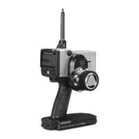
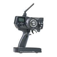
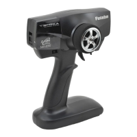
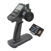
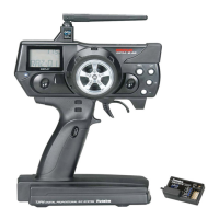
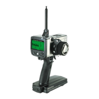
Highlights of the T32MZ-WC transmitter's unique features.
Details on the bidirectional communication capabilities of the FASSTest system.
Explanation of the multiprop function for channel expansion.
Important warnings regarding proper handling of the transmitter antenna.
Instructions on how to adjust the antenna's rotation angle for optimal signal.
Explanation of transmitter status indicators displayed by the LED monitor.
Step-by-step guide for removing and replacing transmitter switches.
Description of the back-side switches (SI, SJ) and their functions.
Explanation of the slide levers (LST, LS, LD, RD, RS, RST) and their operation.
Instructions for operating the touch panel for data entry and navigation.
Guide to adjusting the length of the stick levers for comfortable grip.
Instructions for adjusting the angle of the stick levers for preferred feel.
Procedure for adjusting the tension of the throttle stick's ratchet mechanism.
How to change the function of Elevator-Throttle.
Information on the life of the microSD card and data storage limitations.
Details on connecting the S.BUS connector for telemetry sensor.
Information on the battery charger port and its usage.
Information about the CRSF connector for connecting to TBS.
Explanation of LED indicators for receiver status and link modes.
Guidelines for proper receiver antenna placement for optimal reception.
Overview of the S.BUS2 system and its bidirectional communication.
Explanation of the dual receiver system for enhanced reliability.
Procedure to enable FASSTest 12CH mode with telemetry turned off.
Information on the Receiver Switch ESW-1J and its function.
Details on optional servo usage and compatibility.
Instructions for safely mounting servos and connecting them.
Crucial safety steps for installing receivers and servos properly.
Step-by-step guide for powering the transmitter on and off safely.
A simplified procedure for quickly starting the transmitter.
Instructions on how to view telemetry data on the sub-display.
Detailed steps for linking the transmitter with the R7208SB receiver.
Procedure for adding new model data and linking it with a receiver.
Note on R3004SB receiver compatibility with the model ID function.
Steps to activate functions using the ON/OFF setting.
Navigation methods to return to the home screen or previous screen.
How to check the operational status of functions after activation.
Instructions for locking and unlocking the touch panel for safety.
Step-by-step guide for registering a user name on the transmitter.
Methods to protect user data and names using PIN settings.
Instructions for updating the transmitter's software and firmware.
Information on connecting FASSTest26CH with S.BUS2 and compatible servos.
Procedure for adding new models or calling existing ones.
Selecting the correct model type (airplane, glider) and tail type.
Linking control surfaces like ailerons and elevators as per manual.
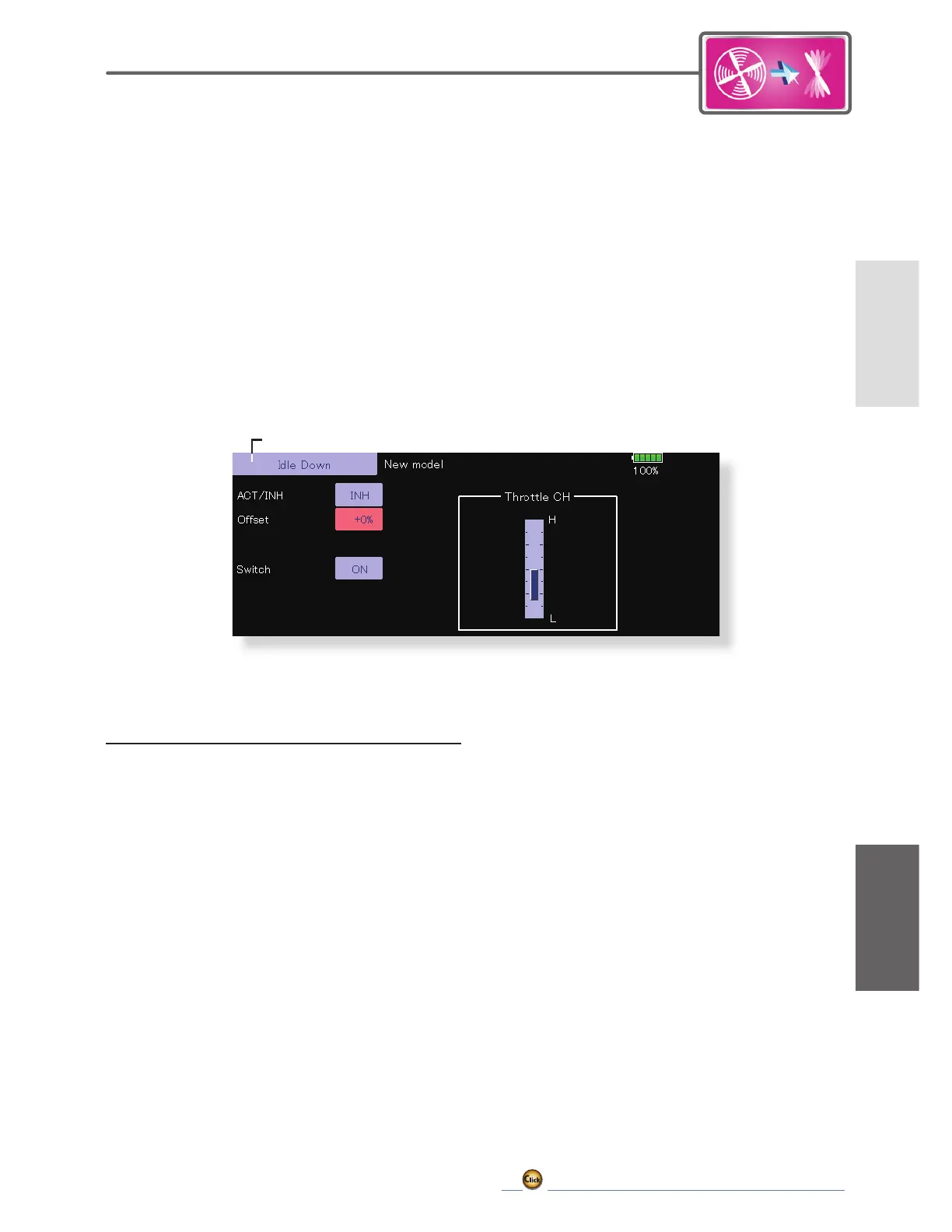
Setting the idle down function for engine speed reduction.
Adjusting throw and operation curve using the AFR function.
Function for controlling airbrakes during landing or diving.
Procedure for adding new models or calling existing ones for helicopters.
Selecting helicopter model type and swash plate type.
Adding and configuring flight conditions for helicopter control.
Adjusting the pitch operation curve based on throttle stick movement.
Setting gyro sensitivity and mode for each model/condition.
Function to easily stop the engine with a throttle cut switch.
Details on special mixing functions like Pit to Needle and Fuel Mixture.
Channel assignments for Airplane, Glider, and Motor Glider model types.
System types supported by the helicopter mode.
System type for FASSTest12CH in helicopter mode.
Overview of functions available within the System Menu.
Trainer compatibility and mode settings for various transmitters.
Explanation of the Normal mode for trainer operation.
Explanation of the MIX mode for trainer operation.
Explanation of the FUNC mode for trainer operation.
Configuring the automatic power-off timer for the transmitter.
Adjusting the brightness of the LCD screen.
Procedure for setting the system clock date.
Procedure for setting the system clock time.
Registering the transmitter's user name.
Setting a PIN to protect user name and data.
Selecting and assigning functions to transmitter switches.
Selecting between Alternate and Momentary modes for switches.
Reversing the operation signal of sticks, switches, and trims.
Setting servo response and hysteresis for stick operation.
Adjusting the stick hysteresis for each condition.
Setting the power switch press time for turning off the transmitter.
Method for reversing stick operation direction.
Controls for playing music files stored on the microSD card.
Functions for managing music files on the microSD card.
Information about individual ID numbers for S.BUS servos.
Steps to change S.BUS servo settings like ID and current settings.
Setting for boost current applied to the motor during servo operation.
Adjusting servo stopping characteristics and brake application.
Setting servo hold characteristic to counteract deviation from target position.
Configuration of DLPH-2 settings for dual link and gyro modes.
Setting the receiver mode for optimal operation.
Selecting the CH mode table for the receiver.
Procedure for performing a ground range check of the radio waves.
Overview of functions available in the Linkage Menu for model setup.
Testing servo movement and positions using Moving Test and Neutral Test.
Procedure to load desired model settings into the transmitter memory.
Changing the name of stored models in the transmitter or microSD card.
Copying model data to another memory for backup or setup.
Selecting the model type (airplane, glider, helicopter) and wing/tail types.
Information on data initialization after changing swash type.
Selecting different wing types for airplanes and gliders.
Choosing rudder types for airplanes and gliders.
Selecting tail types such as normal, V-tail, and elevator.
Setting a picture as a screen image for model identification.
Operations for managing picture files on the microSD card.
Recording voice prompts for transmitter functions.
Procedure for linking receivers to the transmitter.
Using dual receivers for increased channel count and reliability.
Customizing channel assignments for functions and controls.
Changing trim settings for functions and conditions.
Adjusting servo neutral position for fine linkage tuning.
Example of balance function setup for ailerons on large aircraft.
Steps to reverse servo operation direction for individual servos.
Setting fail-safe positions for servos when signals are lost.
Choosing between Hold and Failsafe positions for each channel.
Procedure for setting battery fail-safe based on receiver voltage.
Adjusting left and right servo throws and differential throws.
Setting the limit point for servo travel.
Setting servo delay for position changes.
Procedure for setting throttle cut for engine safety.
Procedure for setting the idle down function to lower engine idle speed.
Limiting swash plate travel to prevent linkage damage.
Setting the neutral point for swash plate compensation.
Adjusting aileron, elevator, and pitch servo rates.
Correcting swash plate movement for proper operation.
Setting the AFR rate for aileron, elevator, and pitch.
Adjusting linkage for correct mixing and direction.
Matching servo speeds for smooth swash plate operation.
Selecting timer mode (count-down/count-up) and setting target time.
Setting switches or sticks for timer start/stop.
Configuring switches for lap time recording.
Setting the timer button operation mode on the home screen.
Displays current and step amount of each digital trim.
Displays current and last operating positions of VRs and slide levers.
Shows current and last operated positions of knobs and levers.
Instructions on viewing telemetry data via the home 2 screen.
Displays receiver battery voltage and voltage alerts.
Displays engine or rotor head RPM data.
Incorporating tonal indications for aircraft ascent/descent rate.
Displays aircraft position data from the GPS sensor.
Displays signal strength from the receiver.
Shows the approximate position of the aircraft on a map.
Registering sensor units and automatically changing slot numbers.
Reallocating sensor slots for desired operation.
Second part of the sensor screen procedure for sensor unit rereading.
Manually changing the sensor unit number for each slot.
Manually entering or changing the sensor unit ID.
Renaming sensors for better identification, especially with multiple sensors.
Creating a personalized User Menu with frequently used functions.
Overview of functions within the Model Menu for common aircraft types.
Switching between Group and Single modes for condition settings.
Changing the display mode for AFR and D/R functions.
Renaming Dual Rate settings for clarity.
Assigning switches for Dual Rate ON/OFF.
Customizing mixing for control or specific aircraft tendencies.
Setting operation curves for mixing functions.
Setting slave channel AFR based on stick input.
Choosing the curve type for mixing adjustments.
Fine-tuning trim settings for mixing functions.
Selecting the mixing setup screen for offset adjustments.
Setting the slave channel for offset mixing.
Fine-tuning trim for offset mixing.
Setting up to five independent sequencers for aircraft functions.
Choosing between Wheel/Basic Door, Wheel/Cycle Door, and Wheel/Boost Door.
Functions available for Airplane, Glider, and EP Glider models.
Dedicated mixing function when a gyro is used.
Improves roll axis performance by operating elevators as ailerons.
Adjusts rudder angles for winglet models.
Setting delay for smooth transitions and cut switch configuration.
Setting up the gyro sensitivity and operation mode.
Wiring instructions for connecting the T32MZ-WC to the GYA553 gyro.
Accessing the basic menu for gyro settings.
Setting the mounting direction of the GYA unit.
Setting wing and tail types for the GYA553.
Selecting the appropriate servo type for the gyro.
Selecting the SB/R2 port for gyro connections.
Setting the correct compensation direction for the gyro.
Adjusting the neutral position for each servo.
Setting the limit for each servo's maximum operation.
Adjusting holding power for servos in AVCS mode.
Resetting individual Config items to initial values.
Activating/deactivating Condition Hold for throttle control.
Adjusting pitch operation curve and trim for helicopter flight.
Adjusting pitch and throttle settings for acceleration.
Creating a basic pitch curve centered near hovering.
Creating a curve for reduced engine speed during idle up.
Method for setting curves and conditions.
Adjusting idle up curves for various flight conditions.
Adjusting throttle hold curve for auto rotation dives.
Methods for setting curve parameters and conditions.
Trimming pitch servo for high side and low side adjustments.
Methods for setting hovering pitch trim and high/low pitch trim.
Adjusting the normal throttle curve for engine speed optimization.
Adjusting idle up curves for reduced engine speed.
Methods for setting throttle curves and idle up conditions.
Trimming the throttle near the hovering point for stable rotor speed.
Methods for setting throttle hover trim and CTRM/NORM modes.
Methods for setting acceleration at elevator, ELE to Camber, and AIL to RUD.
Illustrative examples of throttle hold usage for auto rotation.
Methods for setting throttle hold positions and modes.
Examples of swash mixing for correcting undesirable tendencies.
Methods for setting swash mixing parameters.
Example of throttle mixing for engine speed correction.
Methods for setting throttle mixing and acceleration functions.
Methods for setting needle curve and acceleration/deceleration.
Methods for setting mixing for pitch and rudder operation.
Example settings for three gyros for each condition.
Methods for setting gyro sensitivity and operation mode.
Methods for setting governor speed and RPM.
Overview of gyro settings and connection procedures.
Wireless gyro tuning capabilities and limitations.
List of functions available for wireless gyro tuning.
Procedure for copying gyro data between units.
Initial setup requiring a wired connection to download gyro data.
Subsequent wireless tuning procedures after initial data download.
Overview of information displayed on the transmitter's home screen.
Accessing the basic menu for gyro settings.
Accessing the expert menu for advanced gyro settings.
Selecting setup styles (3D, F3C, L.SCALE) for swash motion.
Setting the mounting direction for the CGY unit.
Selecting the correct servo type for the swash plate.
Changing the swash plate type and its effect on parameters.
Setting servo directions for proper swash plate movement.
Adjusting the neutral position of swash servos.
Selecting aileron, elevator, and pitch direction.
Setting base cyclic throw for gyro calculations.
Saving the full positive collective pitch point into the CGY.
Saving the zero collective pitch point into the CGY.
Saving the full negative collective pitch point into the CGY.
Setting the Cyclic Gyro Base Gain.
Setting the maximum roll and flip rate for cyclic control.
Adjusting aileron control authority for gyro response.
Adjusting elevator control authority for gyro response.
Tuning exponential for cyclic control feel around center stick.
Pre-compensating elevator for nose behavior during collective pitch changes.
Increasing control authority during loaded and high pitch maneuvers.
Selecting the appropriate servo type for the tail rotor.
Setting the correct compensation direction for the yaw axis.
Choosing between CMT, Normal, and AVCS modes for gyro operation.
Activating or inhibiting the governor function.
Inputting the main rotor gear ratio for governor calculations.
Setting the motor pole count for brushless motor sensors.
Activating governor by throttle stick position.
Using a transmitter switch to turn the governor on or off.
Setting battery fail safe for governor and throttle servo.
Selecting the type of governor sensor.
Adjusting governor gain to stabilize helicopter RPM.
Setting minimum throttle for governor command during over-speed.
Fine-tuning swash plate level and cyclic interactions.
Advanced gyro settings for aileron and elevator.
Advanced gyro settings for rudder control.
Setting the neutral position of the rudder servo.
Setting rudder exponential for tail rotor control feel.
Setting delay for tail rotor feel when moving stick from neutral.
Setting delay for tail rotor stop when stick returns to neutral.
Adjusting maximum pirouette speed of the tail rotor.
Feed Forward mixing rate for counteracting torque.
Boosting F/F mixing input for low head speed situations.
Matching helicopter tail response to gyro control.
Adjusting heading hold for stable cyclic control.
Tuning cyclic stop action for the aileron axis.
Tuning cyclic stop action for the elevator axis.
Mixing collective pitch with aileron for swash plate level.
Mixing collective pitch with elevator for swash plate level.
Mixing collective pitch with 2nd elevator.
Mixing elevator with collective pitch for swash plate level.
Mixing elevator with aileron for swash plate level.
Mixing elevator with 2nd elevator.
Elevator linkage compensation for swash plate level.
Setting the compensation direction for elevator.
Matching servo speeds for elevator input.
Selecting the governor working mode (Governor or Limiter).
Displaying rotor or engine RPM.
Adding throttle with cyclic commands for RPM stability.
Setting RPM change rate when increasing RPM.
Setting RPM change rate when reducing RPM.
Setting delay for RPM stabilization after governor engagement.
Switching settings based on flight conditions using Group/Single mode.
Adjusting mixing rates using VR controls.
Suppressing fuselage motion from servo timing changes.
Selecting curve types (Linear, EXP1, EXP2, VTR, Line, Spline).
Adjusting curves based on selected type (Linear, EXP, VTR).
Adjusting RateA and RateB for EXP1 curves.
Adjusting RateA, RateB, P.Pos, and P.Rate for VTR curves.
Selecting switch modes: Single for direct assignment, Logic for combinations.
Setting ON/OFF based on set point with hysteresis.
Symmetrical hysteresis mode for symmetrical neutral positions.
Switching ON/OFF within a range with reversed ON/OFF positions.