Home
Garmin
Transceiver
GNC 255
Garmin GNC 255 User Manual
5
of 1
of 1 rating
138 pages
Give review
Manual
Specs
To Next Page
To Next Page
To Previous Page
To Previous Page
Loading...
GTR 225/GNC 255 TSO Installation Manual
190-01182-02
Page D-20
Rev. A
This page
intentionally left
blank
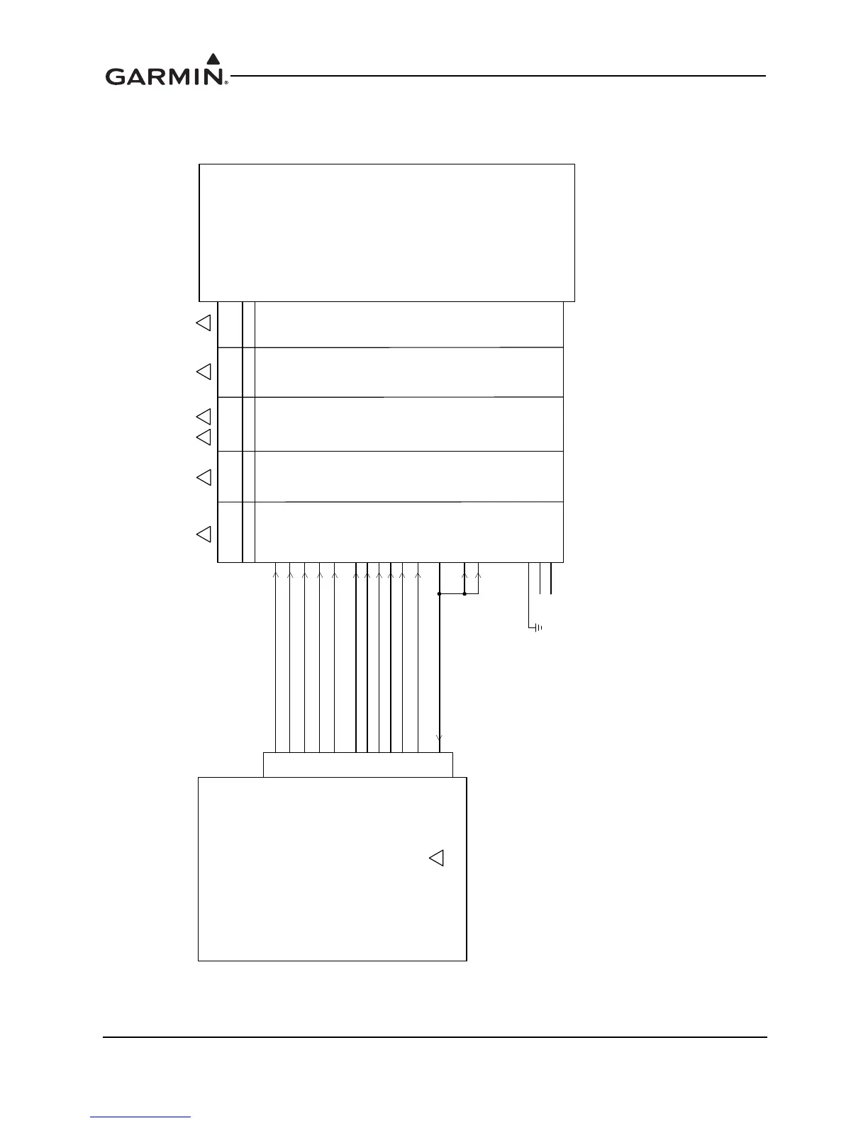
Figure D-1
1. Parallel 2 of 5 DME T
uning Interconnect
Sheet 1 of 2
'0(
0+=$
0+=%
0+=&
0+='
0+=(
.+=$
.+=%
.+=&
;&2'(6(/(&7
6/,3&2'(6(/(&7
0+=$
'0(&20021
%&'&2'(6(/(&7
.+='
.+=(
.+=
0+=(
1$5&2
,'0(
1$5&2
'0(
&2//,16
'0(
&2//,16
'0(
3
3
3
3
%
&
'
+
(
%(1',;.,1*
.1$
&
'
0
-
+
3
*1&
3
$5'0(0+=$
3
$5'0(0+=%
3
$5'0(0+=&
3
$5'0(0+='6(5,$/'0(21
3
$5'0(0+=(
3
$5'0(.+=$6(5,$/'0(+2/'
3
$5'0(.+=%
3
$5'0(.+=&
'0(&20021
3
$5'0(.+='
3
$5'0(.+=(
3
$5'0(.+=
1&
1&
3
129
131
Table of Contents
Default Chapter
7
Table of Contents
7
1 General Description
15
Introduction
15
Equipment Description
15
Table 1-1. TSO-Certified Units
15
Technical Specifications
16
Physical Characteristics
16
General Specifications
16
Display
17
COM Specifications
17
VOR Specifications
18
LOC Specifications
19
Glideslope Specifications
20
Table 1-2. GTR/GNC Current Specifications
21
License Requirements
22
Regulatory Compliance
23
Non-TSO Functions
23
Table 1-3. TSO Authorization and Advisory Circular References
23
Table 1-4. System Functions
23
TSO Deviations
24
FCC Grant of Equipment Authorization
24
GTR/GNC Database
25
Aviation Limited Warranty
25
2 Limitations
27
Installation
27
Aircraft Radio
27
3 Installation Overview
29
Introduction
29
Antenna Considerations
29
COM Antenna Location
29
Interference of GPS
30
GTR/GNC Mounting Considerations
30
Cabling and Wiring Considerations
31
Air Circulation and Cooling
32
Compass Safe Distance
32
4 Installation Procedures
33
Unit and Accessories
33
Miscellaneous Options
33
Table 4-1. Catalog Part Numbers
33
Table 4-2. Standard Kit Accessories
33
Optional Reference Material
34
Installation Materials Required but Not Supplied
34
Accessories Required but Not Supplied
34
Materials Required but Not Supplied (New Installations Only)
34
Special Tools Required
35
Table 4-3. Recommended Crimp Tools (or Equivalent)
35
Coaxial Cable Installation
36
Figure 4-1. Coaxial Cable Installation
36
Equipment Mounting
37
Rack Installation
37
Table 4-4. Socket Contact Part Numbers
37
GTR/GNC Unit Insertion and Removal
38
Unit Replacement
38
Antenna Installation and Connections
38
COM Antenna
38
5 Connector Pinout Information
39
Pin Function List
39
P2001 Connector - COM Board
39
P2002 Connector - NAV Board
41
Power, Lighting, and Antennas
43
Power
43
Lighting Bus
44
Antennas
44
Serial Data - RS-232
44
COM Discrete Inputs
47
VOR/ILS Audio
48
VOR/ILS Discrete Inputs
48
VOR/ILS Indicator
49
Rmi/Obi
51
DME Tuning
52
6 Post Installation Configuration and Checkout Procedures
55
System Configuration Overview
55
Mounting, Wiring, and Power Checks
55
Connector Engagement Check
56
Configuration Mode Operations
56
Figure 6-1. Configuration Mode Home Page
56
SYS Configuration
57
Figure 6-2. Serial Port Page
57
Figure 6-3. DST Display Page
57
Table 6-1. Serial Port Selections
57
Figure 6-4. Intercom Enable Page
58
Figure 6-5. Backlight Page
58
Table 6-2. Intercom Enable Page Selections
58
Table 6-3. Backlight Selections
58
Table 6-4. Photocell Page Parameter Description
59
Figure 6-7. Lighting Bus Page
60
Figure 6-8. Display Information Pages
60
Table 6-5. Lighting Bus Parameter Description
60
NAV Configuration (GNC Only)
61
Figure 6-9. Display Update Page
61
Figure 6-10. CDI Indicator Page
61
Table 6-6. CDI Indicator Selections
61
Figure 6-11. ARINC 429 Page
62
Table 6-7. ARINC 429 Configuration Speed (TX)
62
Table 6-8. SDI Selections
62
Table 6-9. DME Settings
62
COM Configuration
63
Figure 6-12. NAV Information Page
63
Figure 6-13. NAV Software Update Page
63
Figure 6-14. MIC Gain Page
63
Table 6-10. A429 Settings
63
Figure 6-15. COM RX Squelch Page
64
Figure 6-16. COM Information Page
64
Figure 6-17. COM Software Update Page
64
Audio Configuration
65
Figure 6-18. COM Sidetone Page
65
Figure 6-19. MIX NAV Audio Page
65
Figure 6-20. Hi-Fidelity Audio Page
65
Log Functions
66
Figure 6-21. Download Log Page
66
Figure 6-22. Clear Error Logs Page
66
Ground Checks (Configuration Mode)
67
Calibrate Resolver (GNC Only)
67
Figure 6-23. Calibrate OBS Resolver Page
67
Flags Check (GNC Only)
68
Vor/Localizer/Glideslope Indicator (GNC Only)
68
Figure 6-24. Test Analog Flags Page
68
Figure 6-25. Test CDI/VDI Page
68
Lighting Bus Interface Check
69
Ground Checks (Normal Mode)
70
Discrete Input Checkout
70
VHF NAV Checkout
70
NAV Audio Check (Audio Panel Installations) (GNC Only)
70
Table 6-11. Discrete Input Pins
70
Vhf Com
71
Interface Checkout
72
Flight Checks
73
COM Flight Check
73
VOR Flight Check (GNC Only)
73
ILS Flight Check (GNC Only)
73
Software Loading
74
Creating a GTR/GNC Software Loader USB Flash Drive
74
Loading Software to the GTR/GNC
75
Figure 6-26. USB Update Progress
75
Load Database
76
Documentation Checks
76
Airplane Flight Manual Supplement
76
Figure 6-27. Database Update Display
76
Figure 6-28. Verify Database Version
76
7 Periodic Maintenance
77
Equipment Calibration
77
VOR Checks
77
Cleaning
77
Appendix Aenvironmental Qualification Form
79
Appendix Bgtr/Gnc Data Format
81
Aviation Data Format
81
Table B-1. Aviation Output Sentence Format
82
Table B-2. Type 2 Aviation Output Sentence Format
84
NMEA Data Format
85
Table B-3. Input Message Summary
99
Table B-4. Output Message Summary
99
Appendix Cmechanical Drawings
101
Drawing List
101
Figure C-1. GTR/GNC Dimensions
101
Figure C-2. GTR/GNC Mounting Rack
101
Figure C-3. GNC Center of Gravity
101
Figure C-4. GTR Center of Gravity
101
Figure C-5. GTR/GNC Rear Connector Layout Detail
101
Figure C-6. Panel Cutout Detail
101
Figure C-7. GTR Mounting Rack
101
Appendix Dinterconnect Diagrams
111
Drawing List
111
Figure D-1. GTR/GNC System Interface Diagram
111
Figure D-2. GTR/GNC Typical Installation
114
Figure D-3. GTR/GNC Power Lighting Configuration Interconnect
116
Figure D-4. GTR/GNC - Antennas Interconnect
117
Figure D-5. GTR/GNC - Audio Panel Interconnect
121
Figure D-6. GTR/GNC - MIC Interconnect
123
Figure D-7. GTR/GNC - VOR/ILS Interconnect
124
Figure D-8. GTR/GNC Switches Interconnect
126
Figure D-9. RMI OBI Interconnect
127
Figure D-10. GNC - King Serial DME - Remote Mount Interconnect
128
Figure D-11. Parallel 2 of 5 DME Tuning Interconnect
130
Figure D-12. Parallel Slip Code DME Tuning Interconnect
132
Other manuals for Garmin GNC 255
Pilot's Guide
64 pages
5
Based on 1 rating
Ask a question
Give review
Questions and Answers:
Need help?
Do you have a question about the Garmin GNC 255 and is the answer not in the manual?
Ask a question
Garmin GNC 255 Specifications
General
Channels
760
Frequency Range
118.000 to 136.975 MHz
Channel Spacing
25 kHz
Input Voltage
11 to 33 VDC
Dimensions
159 x 50 x 193 mm
Related product manuals
Garmin GNC 255A
132 pages
Garmin GDL 82
68 pages
Garmin GDR 66
40 pages
Garmin GTR 225
132 pages
Garmin GTR 200
85 pages
Garmin GTR 225A
132 pages
Garmin GTR 200B
88 pages
Garmin SL40
38 pages
Garmin AIS 800
14 pages
Garmin VHF 200
60 pages
Garmin AIS 600
12 pages
Garmin Apollo SL40
24 pages

 Loading...