190-01182-02 GTR 225/GNC 255 TSO Installation Manual
Rev. B Page 5-11
5.2.8 VOR/ILS Indicator
VOR/ILS indicator displays both lateral and vertical, To/From indications, lateral and vertical flags and
superflags. Connector P1004 always outputs the VOR/Localizer/Glideslope navigation information. The
VOR/ILS pins on P1004 are used to drive an indicator that displays VOR/ILS information at all times,
regardless of the CDI selection on the GTR/GNC.
VOR/LOC COMPOSITE OUT is a standard VOR/localizer composite output signal which may be used to
drive Left/Right, To/From, and Flag indications of certain navigation indicators that contain an internal
converter.
ILS ENERGIZE output becomes active (low) when VOR/LOC frequency is set to a localizer channel.
5.2.8.1 VOR/ILS Indicator Electrical Characteristics
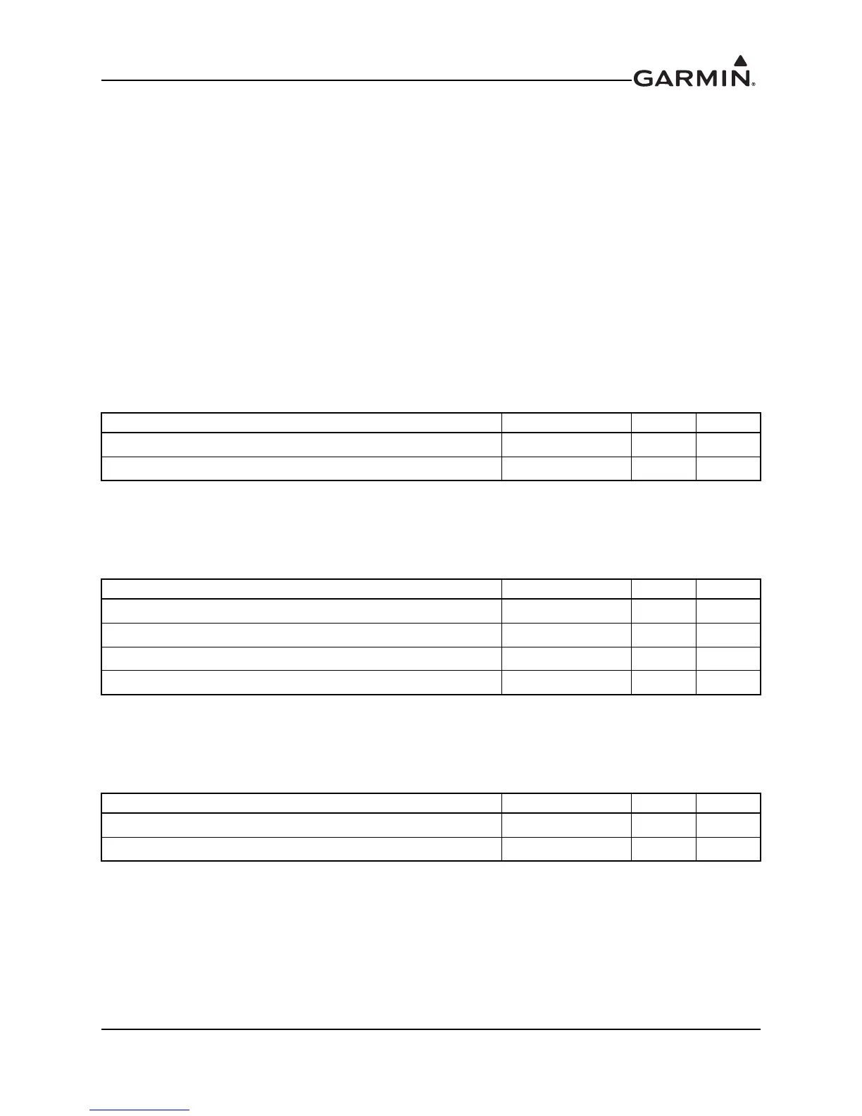
5.2.8.1.1 Superflags
The output supplies not less than 320 mA with the output voltage not less than (AIRCRAFT POWER
-2 VDC) when the flag is to be OUT OF VIEW. The output voltage with respect to ground is 0 +/-250
mVDC when the flag is to be IN VIEW.
5.2.8.1.2 Deviation
Deviation outputs are each capable of driving up to three 1000 loads with 150 mVDC 15 mVDC for
full-scale deflection, 0 mVDC 4.5 mVDC when centered. The drive circuit provides for more than full-
scale deflection with a maximum course deviation output voltage of ±300 mVDC 30 mVDC.
5.2.8.1.3 TO/FROM
TO/FROM output is capable of driving up to three 200 loads. When indicating TO, the output is
+225 ±75 mVDC. When indicating FROM, output is -225 ±75 mVDC. When invalid information is
present (Flag IN VIEW) the TO/FROM output is 0 ±10 mVDC.
Pin Name Connector Pin I/O
VOR/LOC SUPERFLAG* P2002 15 Out
GLIDESLOPE SUPERFLAG* P2002 38 Out
Pin Name Connector Pin I/O
VOR/LOC +LEFT P2002 5 Out
VOR/LOC +RIGHT P2002 6 Out
GLIDESLOPE +UP P2002 34 Out
GLIDESLOPE +DOWN P2002 55 Out
Pin Name Connector Pin I/O
VOR/LOC +TO P2002 1 Out
VOR/LOC +FROM P2002 2 Out

 Loading...