8-4
Data subject to change without notice 7/07. © 2007 GE Drives
8.3 Main Circuit Measurements
The indicated values depend on the type of meter, because the harmonic component is included in the voltage and
current of the main circuit power (input) and the output (motor) side of the inverter. If measuring with a meter for commer-
cial power frequency use, use the meters shown in Table 8.3.1.
The power factor cannot be measured using power factor meters currently available on the market, which measure the
phase difference between voltage and current. If power factors must be measured, measure the power, voltage, and
current on the input side and output side, then calculate the power factor using the following formula:
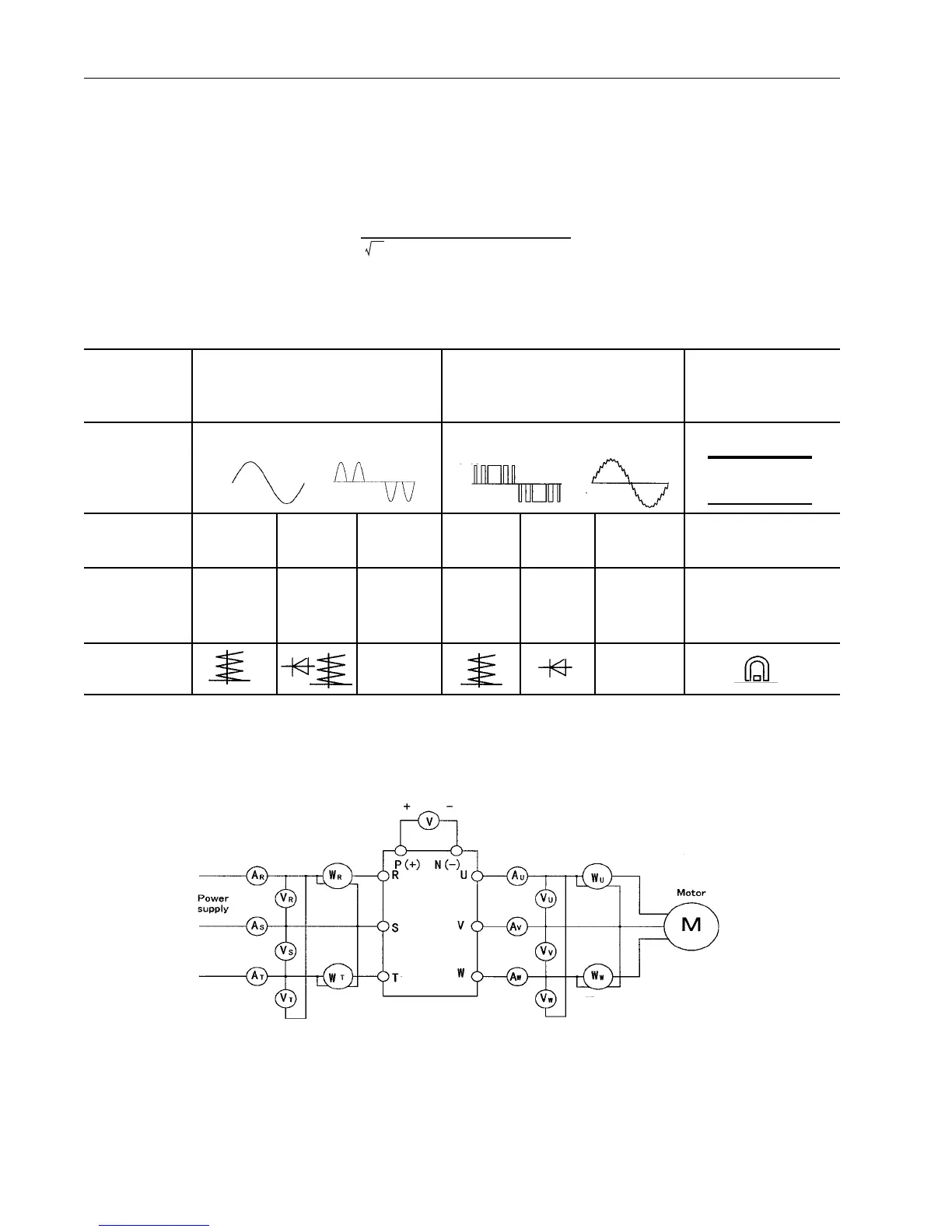
Table 8.3-. Meters for Measuring Main Circuit
Item Input (power supply) Side Output (motor) Side DC Link Circuit
Voltage
P(+) - N(-)
Voltage Current Voltage Current
Meter name Ammeter Voltmeter Powermeter Ammeter Voltmeter Powermeter DC Voltmeter
AR,S,T VR,S,T WR,S,T AU,V,W VU,V,W WU,V,W V
Meter type Moving iron Rectifier or Digital Moving iron Rectifier Digital power Moving coil type
type moving-iron power meter type type meter
type
Symbol
Note: If the output voltage is measured with a rectifier type meter, an error may occur. Use a digital AC power meter to
ensure accuracy.
Power factor =
Power [W]
x 100 [%]
3 x Voltage [V] x Current [A]

 Loading...


