ShieldTermination(CableScreen)
Thesafetygroundterminalprovidesagroundingpointforthemotorcableshield.Themotorcableshieldconnectedtothisterminal(driveend)
shouldalsobeconnectedtothemotorunit(motorend).UseashieldterminatingorEMIclamptoconnecttheshieldtothesafetyground
terminal.
4.3. IncomingPowerConnection
4.3.1. CableSelection
• For1phasesupply,themainspowercablesshouldbeconnectedtoL1/L,L2/N.
• For3phasesupplies,themainspowercablesshouldbeconnectedtoL1,L2,andL3.Phasesequenceisnotimportant.
• ForcompliancewithCEEMCrequirements,refertosection4.10EMCCompliantInstallationonpage14.
• AfixedinstallationisrequiredaccordingtoIEC61800-5-1withasuitabledisconnectingdeviceinstalledbetweentheAF-70andtheAC
PowerSource.Thedisconnectingdevicemustconformtothelocalsafetycode/regulations(e.g.withinEurope,EN60204-1,Safetyof
machinery).
• Thecablesshouldbedimensionedaccordingtoanylocalcodesorregulations.Maximumdimensionsaregiveninsection9.2.
4.3.2. Fuse/CircuitBreakerSelection
• Suitablefusestoprovidewiringprotectionoftheinputpowercableshouldbeinstalledintheincomingsupplyline,accordingtothedatain
section9.2RatingTables.Thefusesmustcomplywithanylocalcodesorregulationsinplace.Ingeneral,typegG(IEC60269)orULtypeJ
fusesaresuitable;howeverinsomecasestypeaRfusesmayberequired.Theoperatingtimeofthefusesmustbebelow0.5seconds.
• Whereallowedbylocalregulations,suitablydimensionedtypeBMCBcircuitbreakersofequivalentratingmaybeutilisedinplaceoffuses,
providingthattheclearingcapacityissufficientfortheinstallation.
• ThemaximumpermissibleshortcircuitcurrentattheAF-70PowerterminalsasdefinedinIEC60439-1is100kA.
4.3.3. OptionalInputChoke
• AnoptionalInputChokeisrecommendedtobeinstalledinthesupplylinefordriveswhereanyofthefollowingconditionsoccur:-
o Theincomingsupplyimpedanceisloworthefaultlevel/shortcircuitcurrentishigh
o Thesupplyispronetodipsorbrownouts
o Animbalanceexistsonthesupply(3phasedrives)
o Thepowersupplytothedriveisviaabusbarandbrushgearsystem(typicallyoverheadCranes).
• Inallotherinstallations,aninputchokeisrecommendedtoensureprotectionofthedriveagainstpowersupplyfaults.Partnumbersare
showninthetable.
4.4. MotorConnection
• Thedriveinherentlyproducesfastswitchingoftheoutputvoltage(PWM)tothemotorcomparedtothemainssupply,formotorswhich
havebeenwoundforoperationwithavariablespeeddrivethenthereisnopreventativemeasuresrequired,howeverifthequalityof
insulationisunknownthenthemotormanufacturershouldbeconsultedandpreventativemeasuresmayberequired.
• ThemotorshouldbeconnectedtotheAF-70U,V,andWterminalsusingasuitable3or4corecable.Wherea3corecableisutilised,with
theshieldoperatingasanearthconductor,theshieldmusthaveacrosssectionalareaatleastequaltothephaseconductorswhentheyare
madefromthesamematerial.Wherea4corecableisutilised,theearthconductormustbeofatleastequalcrosssectionalareaand
manufacturedfromthesamematerialasthephaseconductors.
• ThemotorearthmustbeconnectedtooneoftheAF-70earthterminals.
• Maximumpermittedmotorcablelengthforallmodels:100metresshielded,150metresunshielded.
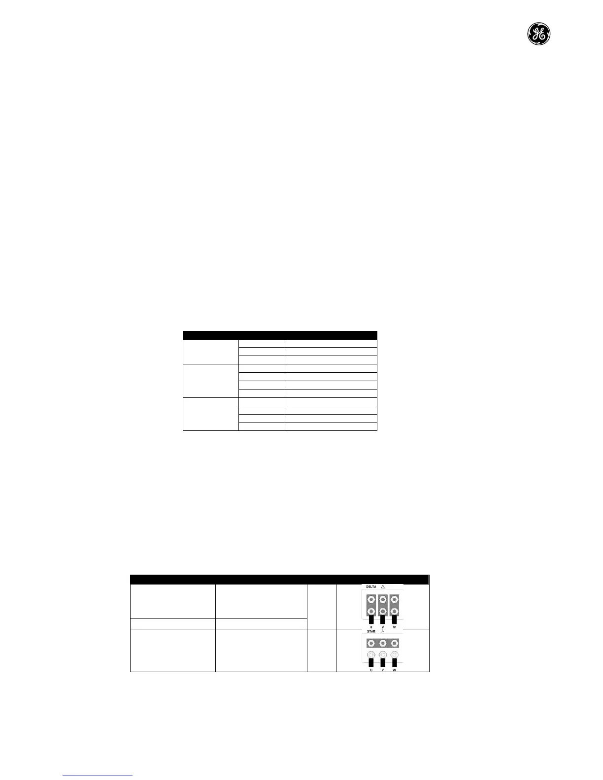
4.5. MotorTerminalBoxConnections
Mostgeneralpurposemotorsarewoundforoperationondualvoltagesupplies.Thisisindicatedonthenameplateofthemotor.This
operationalvoltageisnormallyselectedwheninstallingthemotorbyselectingeitherSTARorDELTAconnection.STARalwaysgivesthehigher
ofthetwovoltageratings.
 Loading...


