General Information and Ratings | Mechanical Installation
General
3
9
3. MechanicalInstallation
3.1. General
TheAF-70shouldbemountedinaverticalpositiononly,onaflat,flameresistant,vibrationfreemountingusingtheintegralmountingholesor
DINRailclip(UnitSizes1and2only).
TheIP20AF-70LPrangemustbeinstalledinapollutiondegree1or2environmentonly.
DonotmountflammablematerialclosetotheAF-70
Ensurethattheminimumcoolingairgaps,asdetailedinsection3.5and3.7areleftclear
EnsurethattheambienttemperaturerangedoesnotexceedthepermissiblelimitsfortheAF-70giveninsection9.1
Providesuitableclean,moistureandcontaminantfreecoolingairsufficienttofulfilthecoolingrequirementsoftheAF-70
3.2. ULCompliantInstallation
Refertosection9.4onpage27forAdditionalInformationforULCompliance.
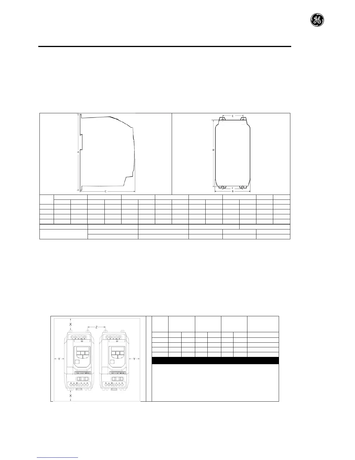
3.3. MechanicalDimensionsandMounting–IP20OpenUnits
3.4. GuidelinesforEnclosureMounting–IP20Units
IP20drivesaresuitableforuseinpollutiondegree1environments,accordingtoIEC-60664-1.Forpollutiondegree2orhigherenvironments,
drivesshouldbemountedinasuitablecontrolcabinetwithsufficientingressprotectiontomaintainapollutiondegree1environmentaround
thedrive.
Enclosuresshouldbemadefromathermallyconductivematerial.
Ensuretheminimumairgapclearancesaroundthedriveasshownbelowareobservedwhenmountingthedrive.
Whereventilatedenclosuresareused,thereshouldbeventingabovethedriveandbelowthedrivetoensuregoodaircirculation.Airshouldbe
drawninbelowthedriveandexpelledabovethedrive.
Inanyenvironmentswheretheconditionsrequireit,theenclosuremustbedesignedtoprotecttheAF-70againstingressofairbornedust,
corrosivegasesorliquids,conductivecontaminants(suchascondensation,carbondust,andmetallicparticles)andspraysorsplashingwater
fromalldirections.
Highmoisture,saltorchemicalcontentenvironmentsshoulduseasuitablysealed(non-vented)enclosure.
Theenclosuredesignandlayoutshouldensurethattheadequateventilationpathsandclearancesarelefttoallowairtocirculatethroughthe
driveheatsink.GErecommendthefollowingminimumsizesfordrivesmountedinnon-ventilatedmetallicenclosures:
Between
Recommended
airflow
DimensionZassumesthatthedrivesaremountedside-by-sidewith
noclearance.
Typicaldriveheatlossesare3%ofoperatingloadconditions.
Aboveareguidelinesonlyandtheoperatingambienttemperatureof
thedriveMUSTbemaintainedatalltimes.
 Loading...


