Modbus RTU Communications | Technical Data
Introduction
9
27
9. TechnicalData
9.1. Environmental
Operationalambienttemperaturerange IP20Drives : -10…60°C(frostandcondensationfree)
above50°C,deratingofoutputcurrent/powerof2.5%per°C
IP66Drives : -10...50°C(frostandcondensationfree)
above40°C,deratingofoutputcurrent/powerof2.5%per°C
Storageambienttemperaturerange : -40…60°C
Maximumaltitude : 2000m.Derateabove1000m:1%/100m
Maximumhumidity : 95%,non-condensing
NOTE ForULcompliance:theaverageambienttemperatureovera24hourperiodfor200-240V,2.2kWand3HP,IP20drivesis45°C.
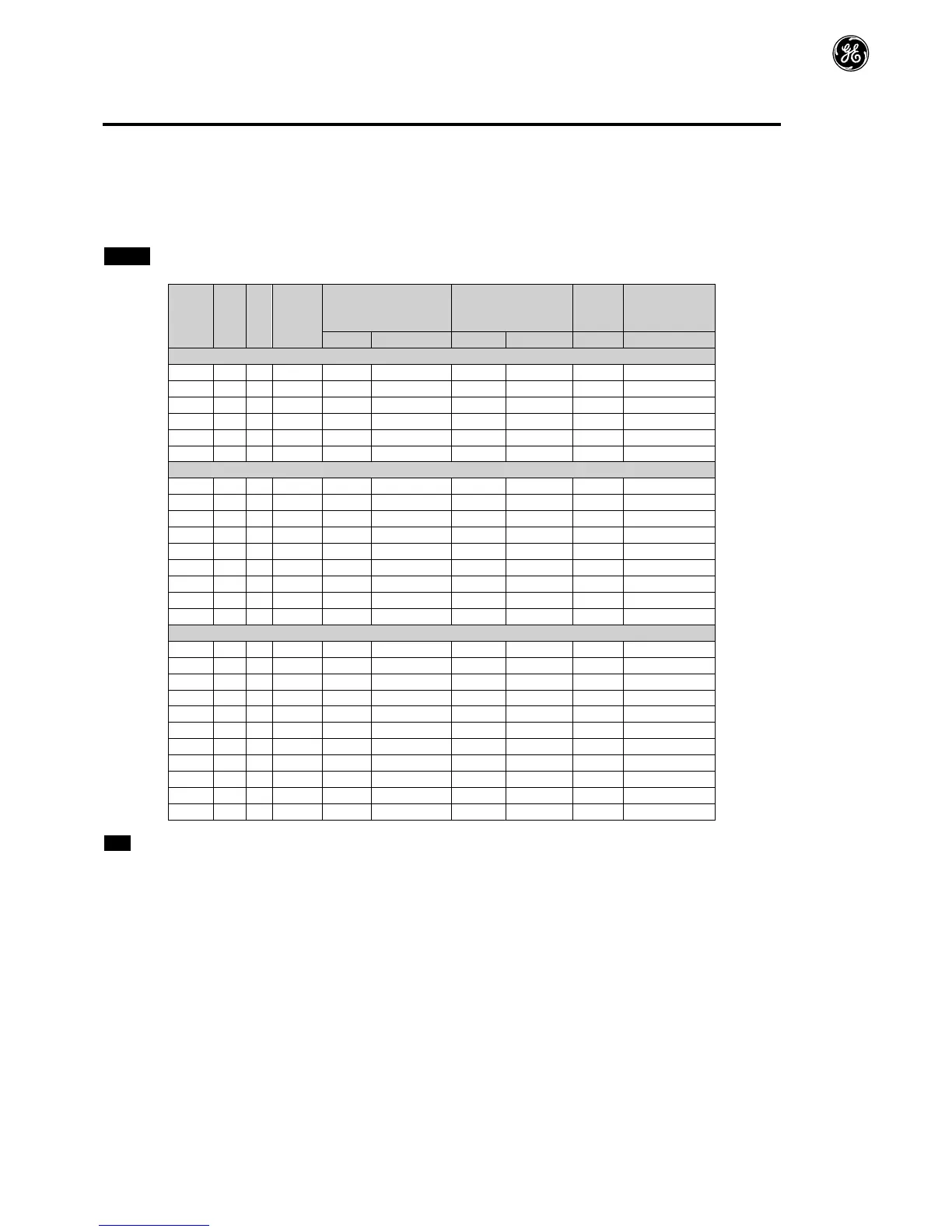
9.2. RatingTables
200-240(+/-10%)V1PhaseInput,3PhaseOutput
200-240(+/-10%)V3PhaseInput,3PhaseOutput
380-480(+/-10%)V3PhaseInput,3PhaseOutput
NoteCablesizesshownarethemaximumpossiblethatmaybeconnectedtothedrive.Cablesshouldbeselectedaccordingto
localwiringcodesorregulationsatthepointofinstallation
9.3. SinglePhaseOperationofThreePhaseDrives
Alldrivemodelsintendedforoperationfromthreephasemainspowersupply(e.g.modelcodes7KLPx3…)maybeoperatedfrom
asinglephasesupplyatupto50%ofmaximumratedoutputcurrentcapacity.
Inthiscase,theACpowersupplyshouldbeconnectedtoL1(L)andL2(N)powerconnectionterminalsonly.
 Loading...


