7. AnalogandDigitalInputMacroConfigurations
7.1. Overview
AF-70usesaMacroapproachtosimplifytheconfigurationoftheAnalogandDigitalInputs.Therearetwokeyparameterswhichdeterminethe
inputfunctionsanddrivebehaviour:
F-12–Selectsthemaindrivecontrolsourceanddetermineshowtheoutputfrequencyofthedriveisprimarilycontrolled.
H-15–AssignstheMacrofunctiontotheanaloganddigitalinputs.
Additionalparameterscanthenbeusedtofurtheradaptthesettings,e.g.
H-16–Usedtoselecttheformatoftheanalogsignaltobeconnectedtoanaloginput1,e.g.0–10Volt,4–20mA
H-30–DetermineswhetherthedriveshouldautomaticallystartfollowingapoweroniftheEnableInputispresent
H-31–WhenKeypadModeisselected,determinesatwhatoutputfrequency/speedthedriveshouldstartfollowingtheenablecommand,and
alsowhetherthekeypadstartkeymustbepressedoriftheEnableinputaloneshouldstartthedrive.
H-47–Usedtoselecttheformatoftheanalogsignaltobeconnectedtoanaloginput2,e.g.0–10Volt,4–20mA
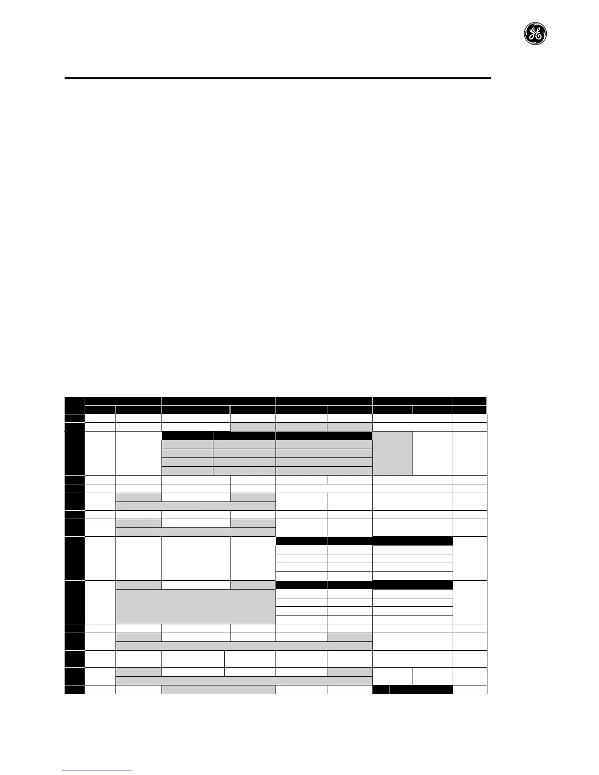
Thediagramsbelowprovideanoverviewofthefunctionsofeachterminalmacrofunction,andasimplifiedconnectiondiagramforeach.
7.2. MacroFunctionsGuideKey
STOP/RUN Latchedinput,ClosetoRun,OpentoStop
ForwardRotation/ReverseRotation Selectsthedirectionofmotoroperation
AI1REF AnalogInput1istheselectedspeedreference
P-xxREF Speedsetpointfromtheselectedpresetspeed
PR-REF PresetspeedsH-20–H-23areusedforthespeedreference,selectedaccordingtootherdigitalinput
status
˄-FASTSTOP(H-24)-˄ Whenbothinputsareactivesimultaneously,thedrivestopsusingFastStopRampTimeH-24
E-TRIP ExternalTripinput,whichmustbeNormallyClosed.Whentheinputopens,thedrivetripsshowing
E-triporptc-thdependingonH-47setting
(NO) NormallyOpenContact,MomentarilyClosetoStart
(NC) NormallyClosedContact,momentaryOpentoStop
FireMode ActivatesFireMode,seesection7.7FireMode
ENABLE HardwareEnableInput.InKeypadMode,H-31determineswhetherthedriveimmediatelystarts,orthe
keypadstartkeymustbepressed.Inothermodes,thisinputmustbepresentbeforethestartsignalvia
thefieldbusinterface
INCSPD NormallyOpen,ClosetheinputtoIncreasethemotorspeed
DECSPD NormallyOpen,CloseinputtoDecreasemotorspeed
KPDREF KeypadSpeedReferenceselected
FBREF SelectedspeedreferencefromFieldbus(ModbusRTU/CANOpen/MasterdependingonF-12setting)
7.3. MacroFunctions–TerminalMode(F-12=0)
 Loading...


