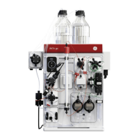
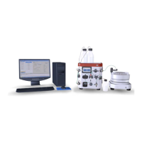
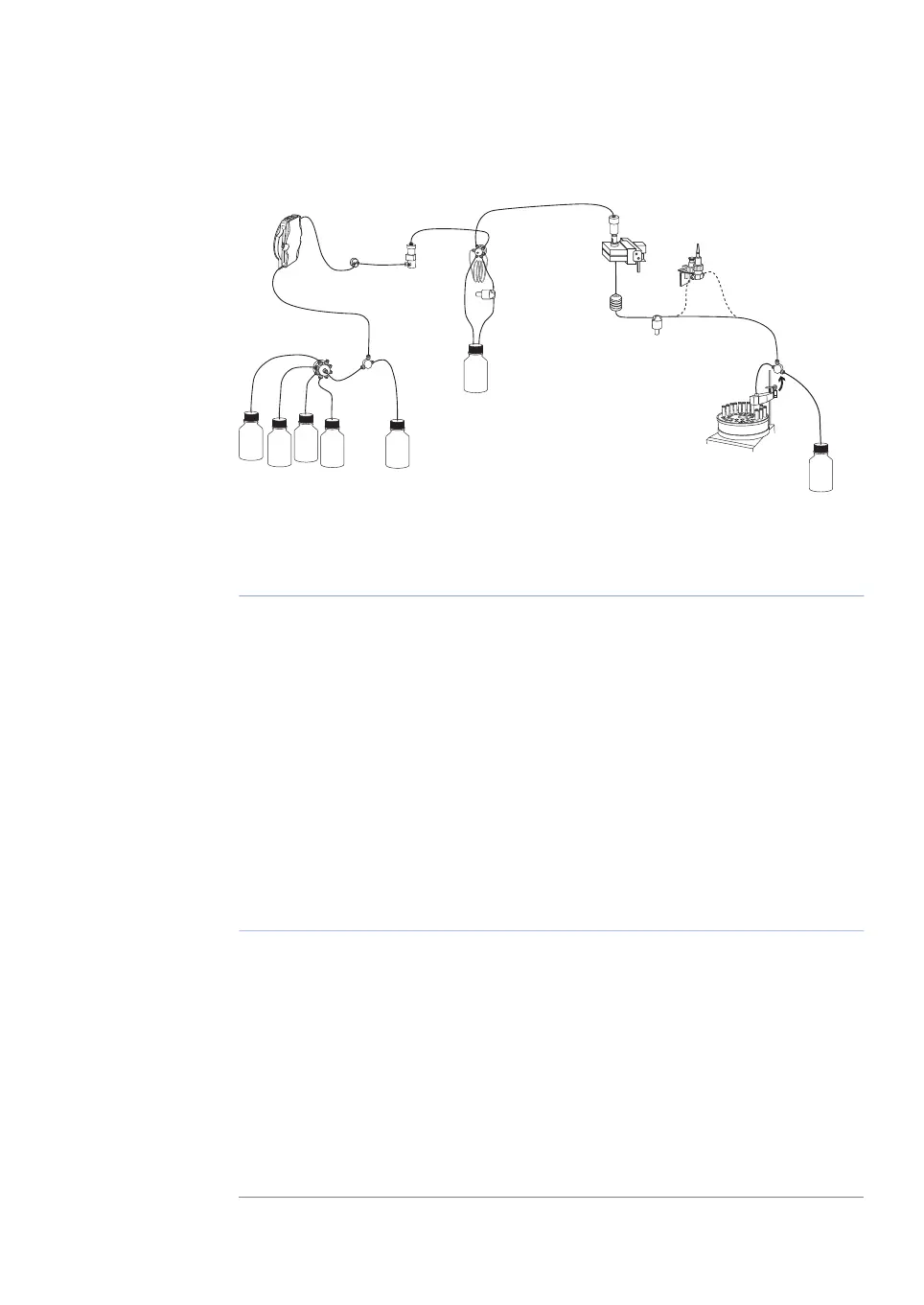
Basic flow path
Figure 1.3: Basic flow path.
DescriptionPartStage
Pump P pumps buffer from a buffer container connected to the
buffer valve V1.
P, V11
To form a gradient the switch valve (SW) can be used to pull liquid
from buffer container (B).
SW, B2
The mixer (M) mixes the buffers.M3
Sample is applied from the sample loop connected to injection
valve (V2) that has been previously filled manually using a syringe.
V24
From the injection valve, the flow is directed to the column, and
then to the UV, Conductivity, and optional pH monitor.
UV, C, pH5
From the monitors, the flow is directed to the Fraction collector
F or the Waste W.
F, W6
1.4 Monitoring and evaluation
PrimeView™ software
PrimeView is a software that allows real time monitoring, evaluation and report generation
on an external computer.
For more information about PrimeView evaluation system and instructions for installation,
see the PrimeView User Manual supplied.
ÄKTAprime plus Operating Instructions 28-9597-89 AB 13
1 Introduction
1.3 Instrument

 Loading...