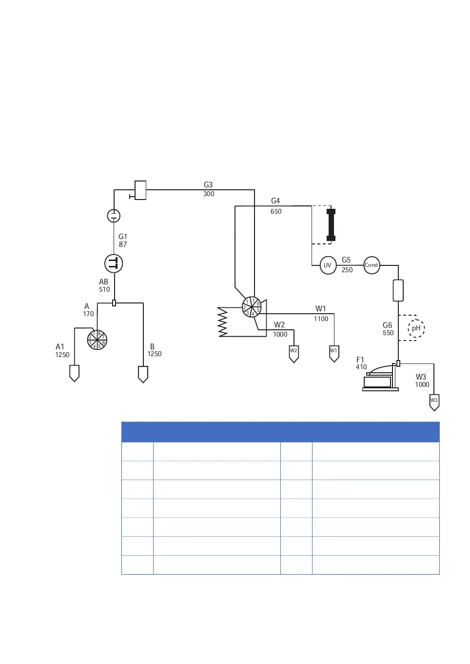
Appendix A Connection diagram - Liquid
flow path
Flow path and components
Cond
1
2
3
4
5
6
7
W1
W2
W3
G5
410
W3
1000
W2
1000
W1
G6
550
F1
G3
300
250
A1
1250
B
1250
1
2
3
4
5
6
7
8
A
170
AB
510
G4
650
UV
pH
1100
G1
87
G2
98
1
2
3
4
5
6
7
8
10
9
11
12
13
14
DescriptionNo.DescriptionNo.
Loop (500 μl)8Buffers1
Waste9Buffer valve2
Column10Gradient switch valve3
Male/Male11System pump4
Flow restrictor (0.2 MPa)12Pressure monitor5
Flow diversion valve13Stop plug6
Fraction collector14Mixer7
ÄKTAprime plus Operating Instructions 28-9597-89 AB 65
A Connection diagram - Liquid flow path

 Loading...