EX2100 User’s Guide GEH-6632 Chapter 1 Equipment Overview
1-5
Hardware Overview
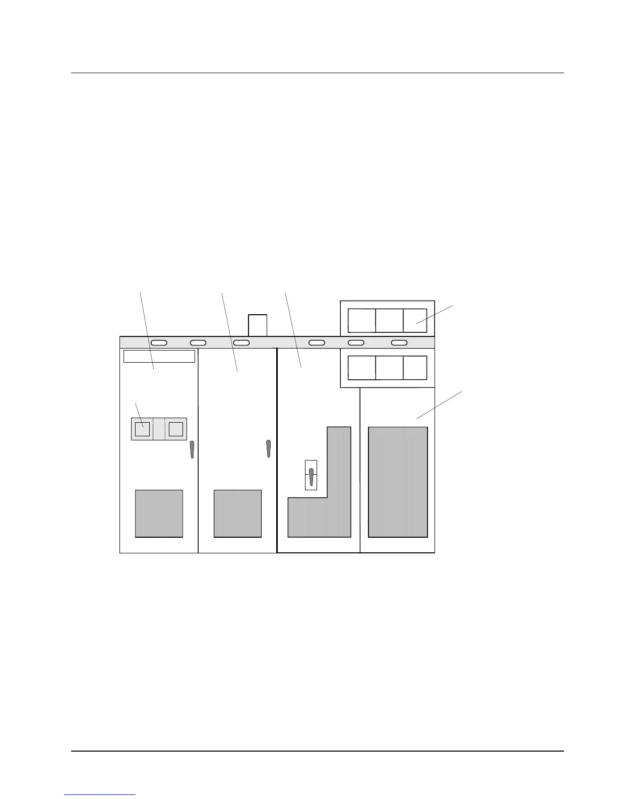
The EX2100 hardware is contained in three cabinets as follows:
• control cabinet for the control, communication, and I/O boards
• auxiliary cabinet for field flashing and protection circuits such as de-excitation
and shaft voltage suppression
• power conversion cabinet for the power SCR cells, cooling fans, dc contactors,
and ac disconnect
The exciter's power converter consists of bridge rectifiers, resistor/capacitor filter
configurations, and control circuitry. An outside view of the cabinets is shown in
Figure 1-3. The components and bridge size vary for different excitation systems and
for the power output required.
Control
Cabinet
Auxiliary
Cabinet
Keypads
Power
Conversion
Cabinet
Fan
Drawers
Contactors &
Disconnects
Figure 1-3. Exciter Cabinets
 Loading...


