4-18
Chapter 4 Terminal Board I/O and Equipment Connections GEH-6632 EX2100 User’s Guide
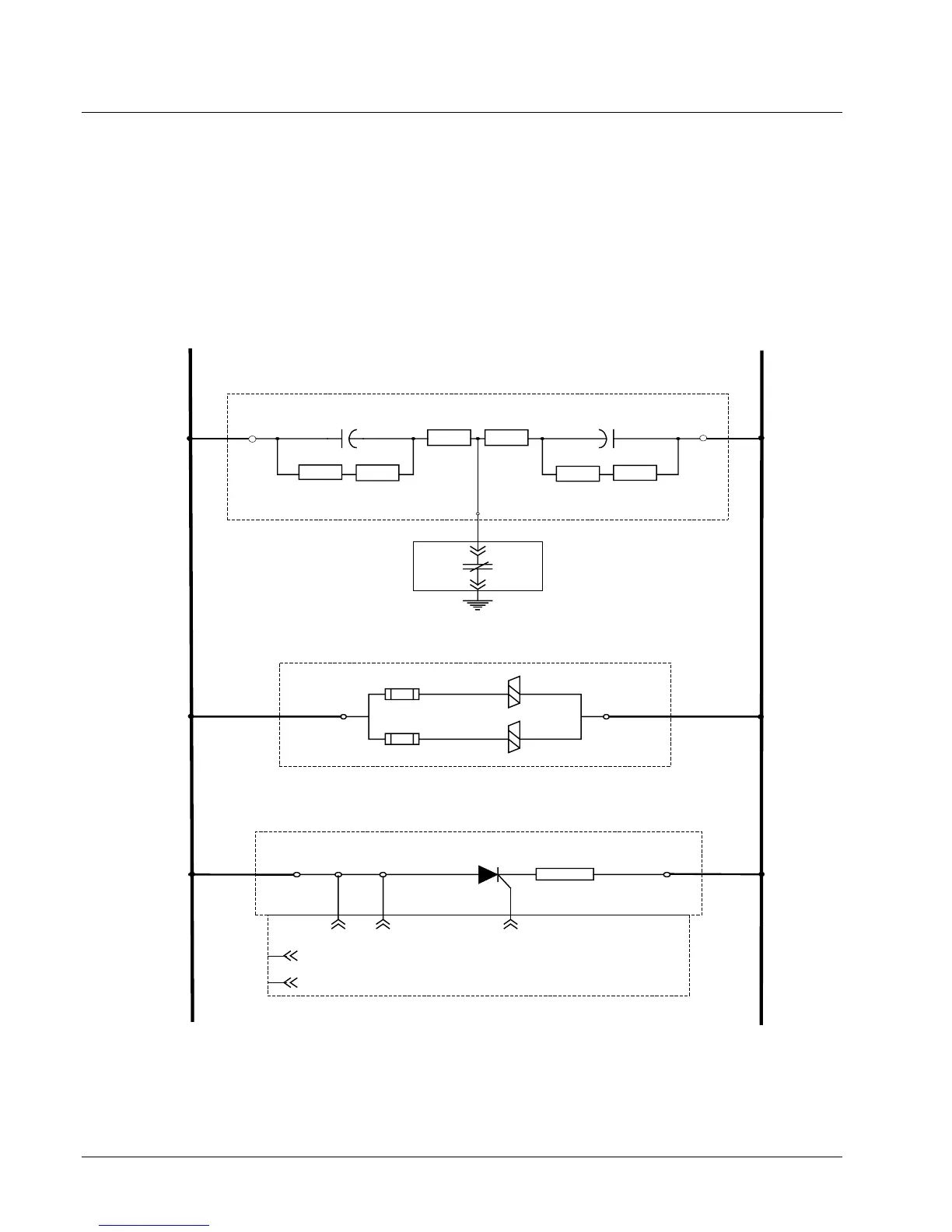
Shaft Voltage Suppressor
Excitation systems, which produce a dc voltage from an ac supply through a solid
state rectification process, cause ripple and spike voltages at the exciter output. Due
to their rapid rise and decay times these voltages are capacitively coupled from the
field winding to the rotor body. This creates a voltage on the shaft relative to ground
that, if not effectively controlled, can damage both journals and bearings. The shaft
voltage suppressor is a filter that conducts the high frequency components of the
induced voltages to ground and limits shaft voltage caused by thyristor commutation
to less than 7 V zero to peak. For the connections to the field, refer to Figure 4-11.
Generator Field -
Generator Field +
TH1 TH2
Thyrite
HSA
CBRO
Crowbar
1
2
HSC
JCY JCX DEPL
EPL1
EPL2
Heatsink
R5 R6
R2
R1
R3 R4
C2
C1
TB1-3
TB1-2
TB1-1
Shaft Voltage Suppressor
53B
AUX
J1-1
J1-2
8
7
Field
Flashing
Figure 4-11 Shaft Voltage Suppressor, Thyrite, and Crowbar
 Loading...


