Section 3
1NSTALLATlON
GUIDELINES
1
INSTALLATION ENVIRONMENT
Install the Drive in an indoor location that meets the
following requirements:
-
The ambient temperature IS between
-10”
C and
+50”
C
(+14”
F to
+122”
F) (Remove the
ventlla-
tlon
cover when the temperature exceeds
+40”
C
[+104”
F] )
-
The relative
humldlty
IS between 20% and 90%.
Avoid
any location subject to condensation, freezing,
orwhere
the Drive would come
In
contact with water.
-
Do not install
In
any location subject to direct sunlight,
dust, corrosive gas, Inflammable gas, or oil
mist.
-
Vibration should be less than 0 6G.
-
The Drive should be Installed at an elevation below
1000 meters (3281 feet). For installation above 1000
meters (3300 feet) the Drive will need to be derated
1% per 333 feet.
Example: 5 HP, 460
Vat,
output current 9 amps.
Application altitude 3900 feet.
% derate
=
(3go&~300)
x 1%
=
1.8%
(9 amps) x
(
w)
= 8.84 amps
derated output current.
Motor derate may also be required,
contact motor manufacturer.
CAUTION:
Because the ambient temperature greatly
affects Drive
life
and retlabilIty, do not install the Drive in
any locatlon that exceeds the allowable temperatures.
I
INSTALLATION MOUNTING
CLEARANCE
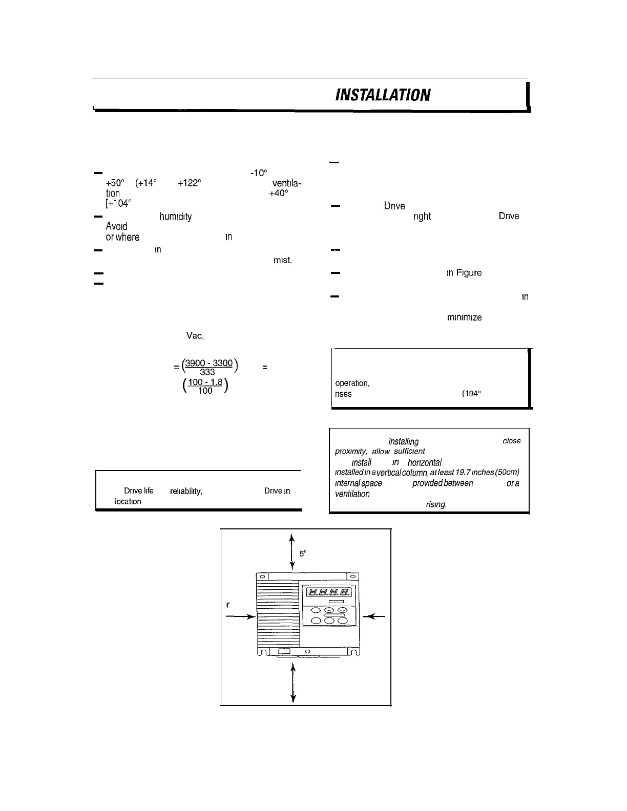
-
Install at a sufficient distance from other equip-
ment, walls, or wiring ducts as shown in Figure
3-1 (these clearances are required to allow the
heat generated by the Drive to escape).
-
Install the
Drive
perpendicular to the ground and
with the lettering
right
side up. (If the
Drive
is
installed upside-down or horizontally, heat build-
up will occur )
-
Mounting screws or bolts should be of appropriate
size for weight of Drive.
-
See the appropriate view
In
Figure
3-2 for the
location of mounting holes.
-
After removing the knockouts in the wiring lead
in
plate, install the rubber bushings supplied to pre-
vent cable damage and to
mmimlze
dust entry.
1
CAUTION:
The mounting wall for the Drive must be
constructed of heat resistant material because during
operation, the temperature of the Drives cooling fins
rises
to approximately 90 degrees C (194” F).
NOTE: When
instaii/ng
two or more Drives in
close
prox/m/ty, allow suffic/ent space as shown in Figure 3-1
and
install
them
In
a
horizontal
row. if they must be
msta//ed/na
verticalcolumn,
at/east
19.7mches
(5Ocm)
Internalspace must be prowdedbetween each one
ora
venf//abon
baffle should be provided to prevent the
ambient temperature from rising.
2”
Ir
more
t
5” or more
2”
or mor
-
t
5” or more
Figure 3-1. DRIVE MOUNTING CLEARANCE
3-l
 Loading...


