– 19 –
3. Continue this process all the way around the
inner panel until all clips have been inserted.
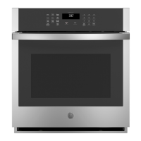
4. With a small screwdriver, tuck the loose ends of
the gasket into the slots at the center bottom of
the door panel. Be sure to leave a 6-in. gap in
the gasket at the bottom of the door.
5. After the gasket has been installed, wipe a finger
around the outer perimeter of the gasket, press-
ing it up against the side of the inner panel. This
will assure that the gasket is fully seated.
Door Hinge Assemblies
The door hinge comes as a complete assembly.
For the hinges to operate properly, the hinge arms
must be perpendicular to the door liner and parallel
to each other with the door in the open position.
Door Hinge Replacement
1. Remove the door. Refer to Lift-Off Oven Door.
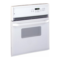
2. Remove 3 or 4 screws (depending on model)
from the bottom door frame.
3. Remove 2 screws from each side of the door,
and separate the door liner and the outer glass
assembly.
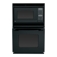
4. Remove 3 or 4 screws (depending on model)
from the door liner to remove each door hinge
assembly.
Note: When assembling, make sure the hinge
arms are parallel to each other and perpendicular
to the door liner. If not, the hinge may bind on the
receiving channel of the door.
Note: If the new hinge is not in the cocked and
locked position after installing, place the bottom of
the door against a firm surface and push the hinge
arm down to the cocked position. Pull the hinge
lock back against the door liner surface to lock the
hinge in this position.
3 Screws
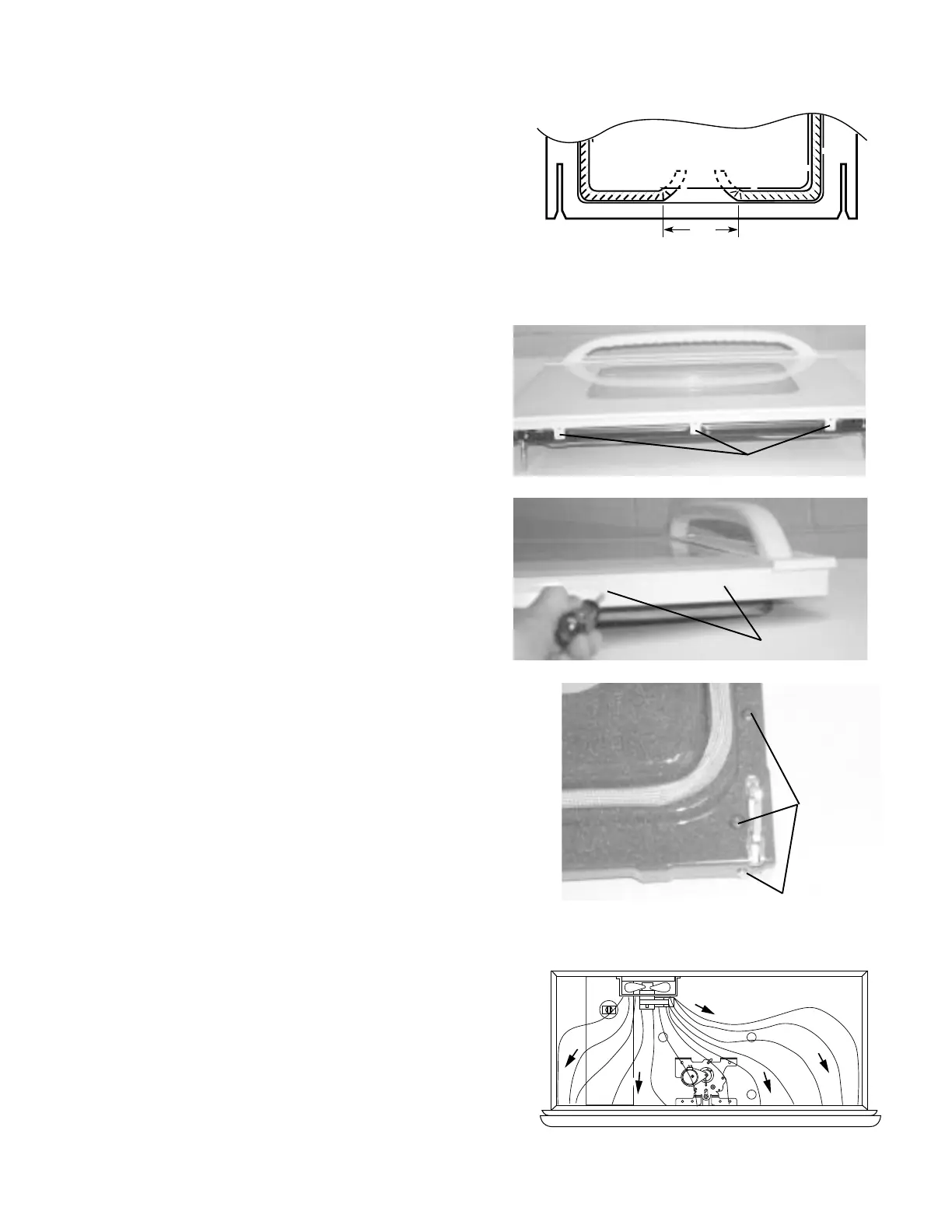
Component Compartment Airflow
The component compartment contains a fan
located on the rear wall of the compartment. Fan
blades pull air in from the back of the unit, circulate
it in the compartment area to cool the compo-
nents, and exhaust it through the louvers below the
control panel.
The fan turns ON when the START pad is de-
pressed after selecting a cook mode. It turns OFF
when the CLEAR/OFF pad is depressed or when
the COOK TIME has ended.
2 Screws
3 Screws
 Loading...