– 36 –
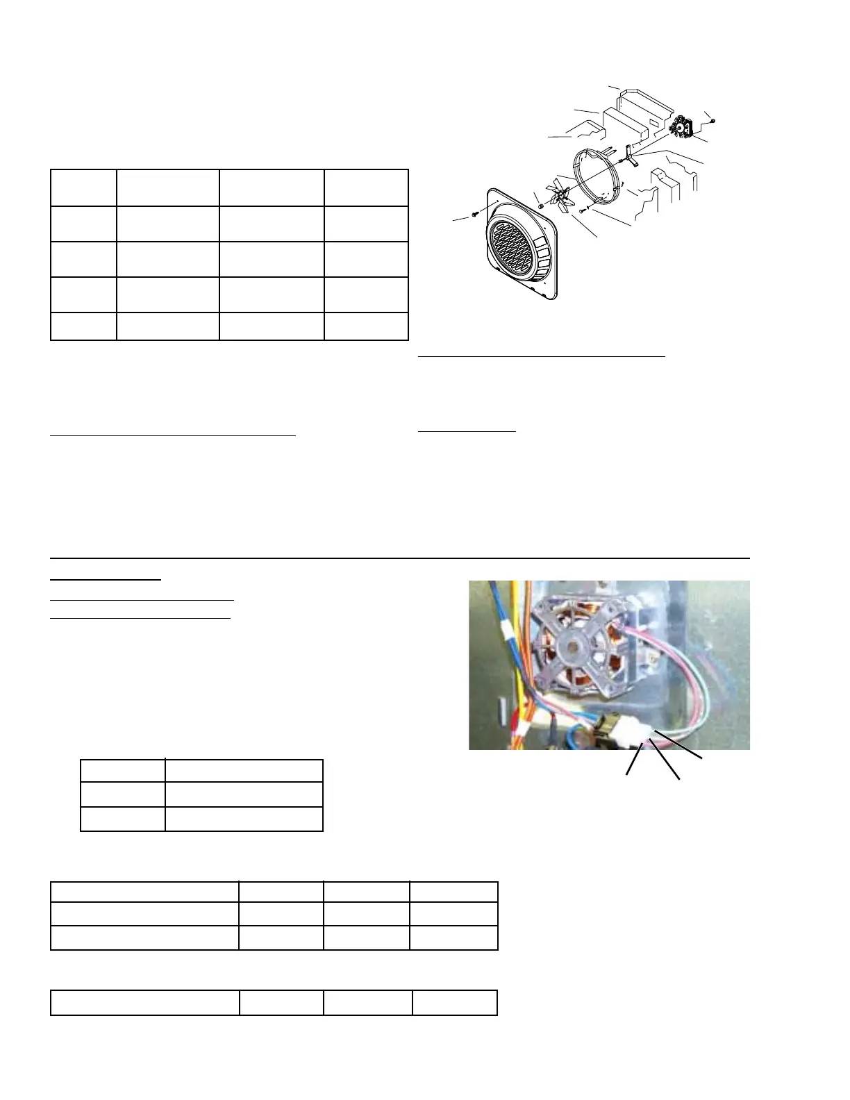
Convection Bake Element and
Fan Assembly
For more even baking, the new convection fan
rotates in both directions depending on mode (see
table).
The convection bake element and fan assembly
are located on the back wall of the oven liner
behind the panel with the screen in the center.
To access convection bake element:
1. Disconnect the power to range; remove the
oven door and the oven racks.
2. Remove 4 screws from the mounting panel (2
on each side) and pull forward.
Assumptions :
1. Checked relays are providing corrected voltage
outputs.
2. Control Compartment connectors are connected properly.
3. Capacitor will fail as an open or short.
Point 1 CW Windings
Point 2 CCW Windings
Point 3 Conv Fan Neutral
No Power Applied Measure Resistance
Possible Failure Modes Pt 1 to 3 Pt 2 to 3 Pt 1 to 2
Conv. Fan CW winding Open Infinite n/a n/a
Conv. Fan CCW winding Open n/a Infinite n/a
Capacitor Short n/a n/a 0
Power Applied Measure Voltage
Possible Failure Modes Pt 1 to 3 Pt 2 to 3 Pt 1 to 2
Capacitor Open = Pt 2 to 3 = Pt 1 to 3 n/a
To remove convection bake element:
Remove 3 screws mounting the element to the
back wall and pull forward. Disconnect the wires.
To service fan:
Note: Convection fan blade nut has left-handed
threads.
Fan blade can be replaced from inside oven.
Oven must be removed from installation to
access convection fan motor.
Troubleshooting:
SCREWS
(4)
FAN
BLADE
NUT
OVEN
LINER
OVEN
INSULATION
OUTER
BACK
PANEL
CONV.
FAN
MTG.
SCREWS
(3)
CONV.
FAN
COLLAR
MTG.
SHAFT
MOUNTING
SCREWS
(3)
FAN
BLADE
Convection fan not running.
Make the following checks:
Point 3
(BLUE)
Point 1
(RED)
Point 2
(GRAY)
Note: Oven must be removed
from installation for access to the
convection motor shown above.
Refer to the schematic in the
back of this manual for circuitry
for your specific model.
noitcevnoC
edoM
esiwkcolC-retnuoC
emiTnoitatoR
neewteBemiTtseR
snoitceriD
esiwkcolC
emiTnoitatoR
noitcevnoC
tsaoR
YLNO
esiwkcolC-retnuoC
ENONENON
noitcevnoC
kcaR-itluM
sdnoceS04sdnoceS01sdnoceS02
noitcevnoC
kcaRelgniS
ssetuniM3sdnoceS01setuniM3
foorPetuniM1setuniM01etuniM1
 Loading...