Chapter 2: Installation
14 Kilsen KFP-CF Series Installation Manual
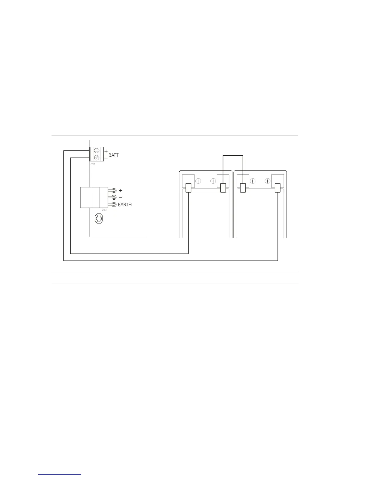
Connecting the batteries
The control panel requires two 12 V, 7.2 or 12 Ah rechargeable, sealed, lead-acid
batteries (see “Compatible batteries” on page 47).
Batteries must be installed in series, at the base of the control panel cabinet. Use the
battery lead and bridge provided and connect batteries to the BATT connector on the
control panel PCB, as shown below. Polarity must be observed.
Note: If the control panel indicates a Supply Fault, then the batteries may need to be
replaced. See “Battery maintenance” on page 47.
Figure 7: Connecting the batteries
Caution: No other equipment may be connected to the BATT connector.
Other connections
Connecting auxiliary equipment
Connect the auxiliary equipment to 24 AUX as shown in Figure 4 on page 9. The
24 VDC auxiliary output is supervise
d for short circuit and voltage output.
Connecting alarm and fault relays
Connect the alarm and fault equipment to the ALARM and FAULT relays.
Each potential-free relay output will be activated in an alarm or fault situation
respectively. The fault relay output is powered when there is no fault.
The maximum contact rating for each relay circuit is 2 A / 30 VDC.
 Loading...


