GE MEDICAL SYSTEMS LOGIQ A1 BASIC SERVICE MANUAL
REV 2 5176463-100
14
2-2-5 Assembling LOGIQ A1
Assembling system
1.
Get the probe out of package and put in into the special probe holder.
2.
Make sure the mainframe off before connecting probe.
3.
Make sure any probe connects to the following socket:
a.
Turn the handle key to the position of 3 o’clock.
b.
Connect the linker of probe to the probe socket of main unit.
c.
Turn the handle key to the position of 12 o’clock.
4.
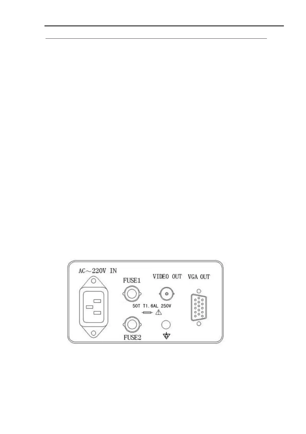
Connect the inner pin to AC socket in the back panel of main unit, connect another
pin to the hospital power socket with the regular press output, do not use three-pin
to two-pin commutator, that will destroy the grounded safety.
5.
Open the keyboard through the lock on the top of main unit.
Note:
Do not move or institute mainframe when dropping the keyboard.
2-2-6 Installation of optional accessories
1.
Connect VGP to suitable power socket, connect Video out port to Video In of VGP
with BNC-BNC cable in the back panel of LOGIQ A1.
Install the accessories
Illustration 2-1
 Loading...


