GE
Direction 5370626-100, Revision 18 LOGIQ e/LOGIQ e Vet/LOGIQ i/Vivid e Basic Service Manual
Chapter 3 System Setup 3-19
3-6-5-3 This section indicates the pin assignment for each connector.
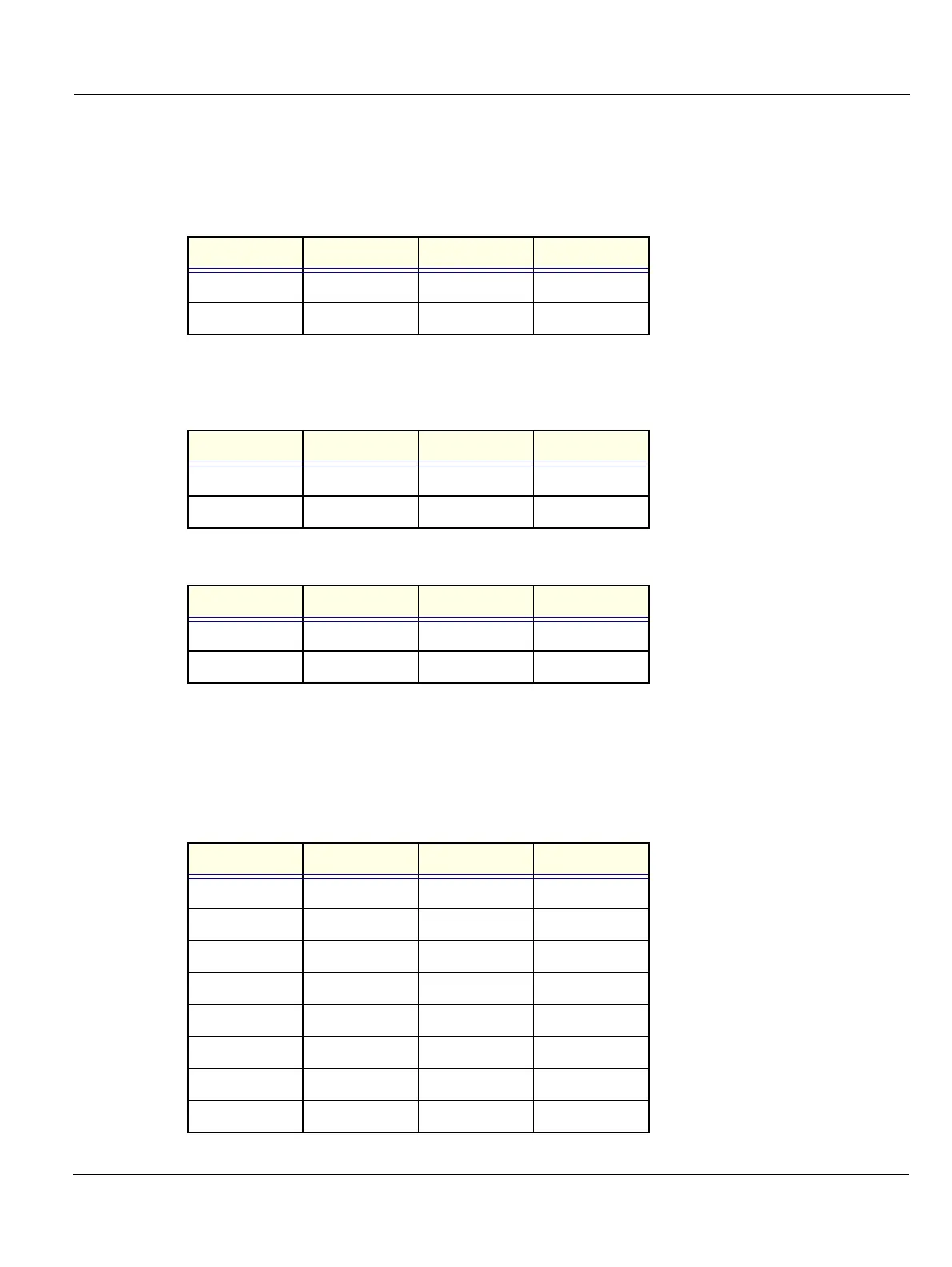
1. Pin Assignment of DC input
Connector: 4 Pin, Female
Table 3-9 Pin Assignments of DC input
2. Pin Assignment of USB
Table 3-10 Pin assignment of USB1
Table 3-11 Pin assignment of USB2
3. Pin assignment of RS232C for external VGA
Connector: D-SUB, 15Pin, Female
Table 3-12 Pin Assignments of RS232C for External VGA
Pin No. Signal Pin No. Signal
1+20V3GND
2+20V4GND
Pin No. Signal Pin No. Signal
1 +5VDC 3 DATA+
2 DATA- 4 GND
Pin No. Signal Pin No. Signal
1 +5VDC 3 DATA+
2 DATA- 4 GND
Pin No. Signal Pin No. Signal
1RED9 N/A
2 GREEN 10 SGND
3BLUE11 N/A
4N/A12N/A
5 GND 13 HSYNC
6 RGND 14 VSYNC
7 GGND 15 N/A
8BGND16
 Loading...


