GEK - 105560
24
6.1 READOUT SEQUENCE
This is the typical sequence for the MLJ as well as the power-up sequence. It is divided into a series of
“Functions”, each corresponding to different types of information. These functions are numbered from
1 to 12 and are identified by the letter F followed by the number of the function.
In normal operation, and shortly after being connected,
the MLJ displays the state of the line and bus. The left-
hand segment represents the state of the line and the
right-hand segment, the state of the bus. If both are live,
two horizontal upper segments will light up. This is the
reading assigned to the last function,
F12
.
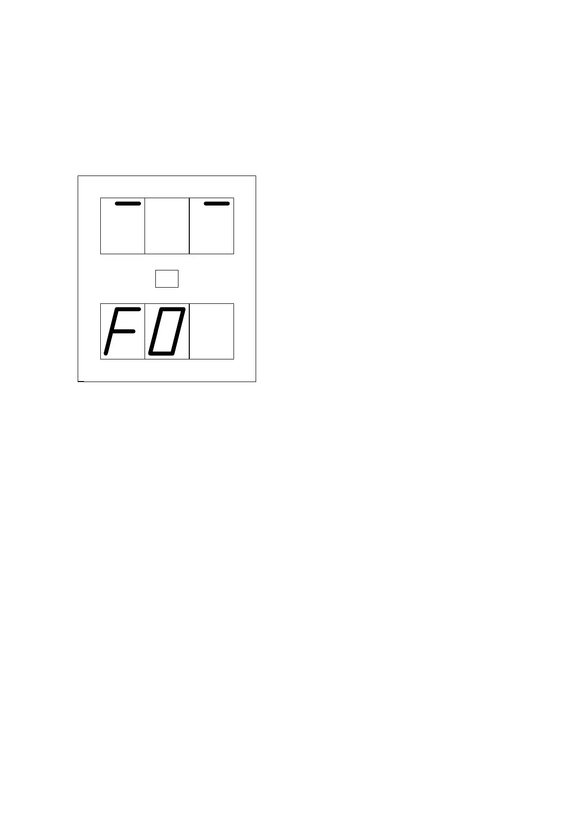
If the
ENTER
button is now pressed and held down,
F0
will appear.
While the button is pressed, this code will remain on the
display. It tells us that we are in Function 0 of the Readout
Sequence. This function, which will appear as soon as the
button is released, indicates the Status of the relay.
If the ENTER button is pressed a second time, the
second function,
F1
will appear. This function shows the
value of the line voltage, and will be seen as soon as the
ENTER
button is released.
In this fashion, pressing and releasing the
ENTER
button, we can go through the entire Readout
Sequence. On the front of the relay, under the word “
DISPLAY
” there is a list of all of the functions.
They are listed below:
F0:
STATUS State of relay
F1:
VL Line voltage
F2:
VB Bus voltage
F3:
∆
V
Modulus of voltage difference
F4:
∆θ
Phase angle
F5:
∆
f
Frequency slip
F6:
LAST VL VL in the last close enable
F7:
LAST VB VB in the last close enable
F8:
LAST
∆
V
∆
V in the last close enable
F9:
LAST
∆θ ∆θ
in the last close enable
F10:
LAST
∆
f
∆
f in the last close enable
F11:
TEST Display test, LEDs and inputs
F12:
VL VB State of line and bus
Each of these functions are covered in further detail.
ENT