GEK - 105560
25
6.1.1 F0: State of relay, error codes
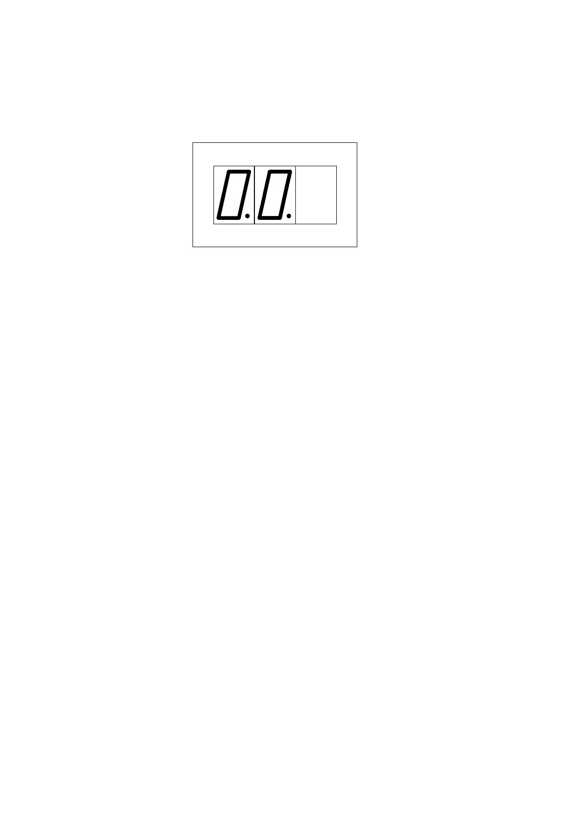
The state of the MLJ presented by a two-digit code. The decimal points remain lit so as to distinguish
the code from other readings. A 00 code (everything correct) would be represented as follows:
The state codes for the MLJ, in order of priority, are:
0.0.
No defects
8.0.
ROM failure. The program memory has failed.
8.1.
Failure in writing to EEPROM
8.2.
RAM program failure
0.1.
Setting failure. The settings stored are incorrect. This error is also produced when the
EEPROM memory is new (in which case the default settings are stored).
0.4.
Measurement error (defect in the analog circuits).
The error
0.1.
can be corrected by the user by simply modifying the value of any of the settings.
The rest of the errors indicate an electronic failure; if such errors are persistent, maintenance will be
required. If the error is transitory and disappears, the MLJ will reset and start up in the normal fashion.
6.1.2 F1, F2: VL, VB, Voltage in line and buses
These readings supply the RMS values of voltages in real time.
6.1.3 F3:
∆
V Voltage difference module
The relay vectorially subtracts the line and bus voltages; the modulus of the subtraction is what is
represented in this reading. See the graphic of phasors in the APPLICATION section.
6.1.4 F4:
∆θ
Phase angle
The phase angle is always given in absolute values which fall between 0 and 180º. The angle
measurement is not influenced significantly by variations in voltage.
If the line or bus voltage is less than 9 volts, since the relay does not consider the angle measurements
precise enough in such conditions, three horizontal lines will appear on the screen(overflow indicator).
6.1.5 F5:
∆
f Frequency Slip
This reading supplies the frequency slip in mHz, calculated based on the difference in frequencies.
For the same reason mentioned in the previous section, if voltage is less than 9 volts, three horizontal
lines will appear on the screen.
 Loading...


