S3 Logic Inputs745
Transformer Management Relay
Setpoints
http://www.GEindustrial.com/multilin
5–38
GE Multilin
• ANALOG OUTPUT 1(7) VALUE: Select the measured parameter below to be
represented by the mA DC current level of Analog Output 1(7).
• ANALOG OUPUT 1(7) RANGE: Select the full-scale range of output current for
Analog Output 1(7).
• ANALOG OUTPUT 1(7) MIN/MAX: Enter the value of the selected parameter
which corresponds to the minimum/maximum output current of Analog Output
1(7).
S3 Logic Inputs
Description The are two types of digital inputs: Logic Inputs have physical terminals for
connecting to external contacts; Virtual Inputs provide the same function as logic
inputs, but have no physical external connections. A setpoint defines the state of
each in Virtual Input in terms of “On” or “Off”.
There are 16 each of logic and virtual inputs. The state (‘asserted’ or ‘not asserted’)
of each logic or virtual input can be used to activate a variety of predefined logic
functions, such as protection element blocking, energization detection, etc. In
addition, any logic or virtual input can be used as an input in FlexLogic™ equations
to implement custom schemes.
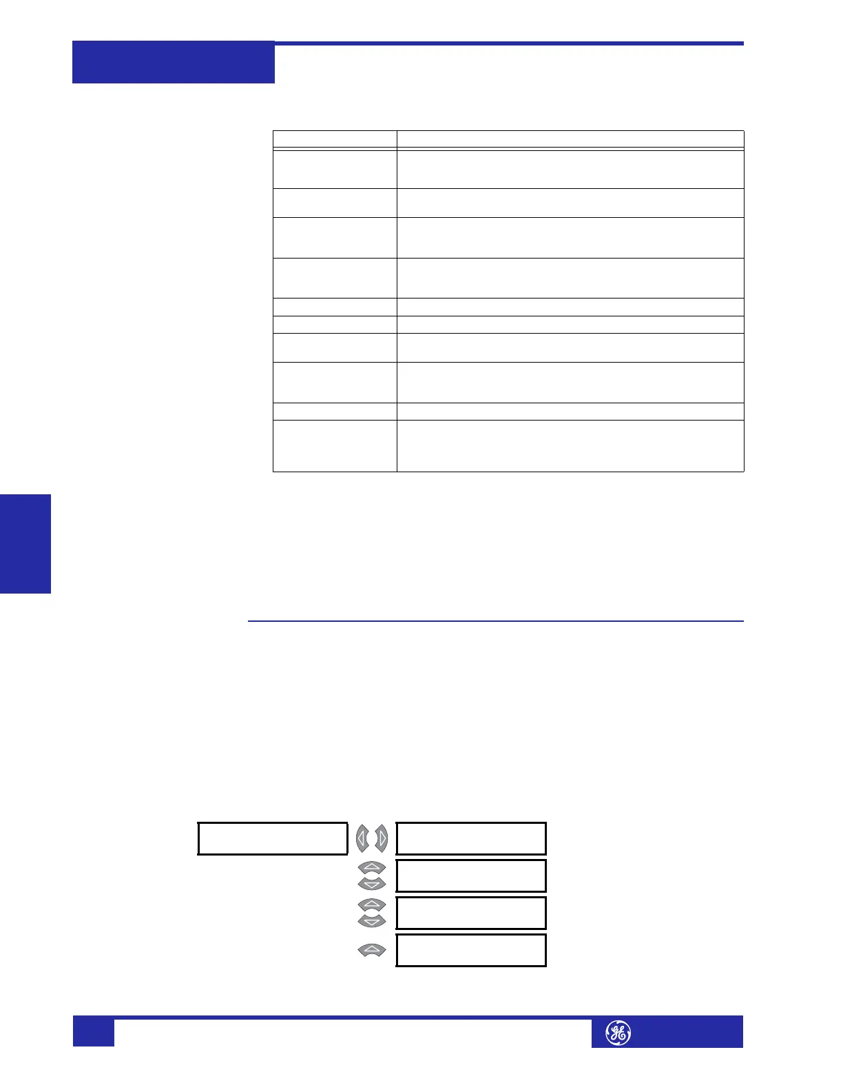
Logic Inputs 1 to 16 PATH: SETPOINTS !" S3 LOGIC INPUTS ! LOGIC INPUTS ! LOGIC INPUT 1(16)
Parameter Description
W1(3) ΦA Current
W1(3) ΦB Current
W1(3) ΦC Current
Select to monitor the RMS value (at fundamental frequency)
of the Winding 1(3) Phase A, B, and C current inputs.
W1(3) Loading Select to monitor the Winding 1(3) load as a percentage of
the rated load for that winding.
W1(3) ΦA THD
W1(3) ΦB THD
W1(3) ΦC THD
Select to monitor the total harmonic distortion in the
Winding 1(3) Phase A, B, and C current inputs.
W1(3) Derating Select to monitor the harmonic derating factor (that is, the
derated transformer capability while supplying non-
sinusoidal load currents) in Winding 1(3).
Frequency Select to monitor the system frequency.
Tap Position Select to monitor the onload tap changer position.
Voltage Select to monitor the system voltage as measured from the
voltage input.
W1(3) ΦA Demand
W1(3) ΦB Demand
W1(3) ΦC Demand
Select to monitor the current demand value of the Winding
1(3) Phase A, B, and C current inputs.
Analog Input Select to monitor the general purpose analog input current.
MaxEvnt W1(3) Ia
MaxEvnt W1(3) Ib
MaxEvnt W1(3) Ic
MaxEvnt W1(3) Ia
Select to monitor the maximum captured RMS value (at
fundamental frequency) of the Winding 1(3) Phase A, B, C,
and Ground current input for all events since the last time
the event recorder was cleared.
! LOGIC INPUT 1 [!] INPUT 1 FUNCTION:
Disabled
Range: Enabled, Disabled
MESSAGE
INPUT 1 TARGET:
Self-Reset
Range: None, Latched, Self-Reset
MESSAGE
INPUT 1 NAME:
Logic Input 1
Range: 18 alphanumeric characters
MESSAGE
INPUT 1 ASSERTED
STATE: Closed
Range: Open, Closed
 Loading...


