S4 Elements745
Transformer Management Relay
Setpoints
http://www.GEindustrial.com/multilin
5–48
GE Multilin
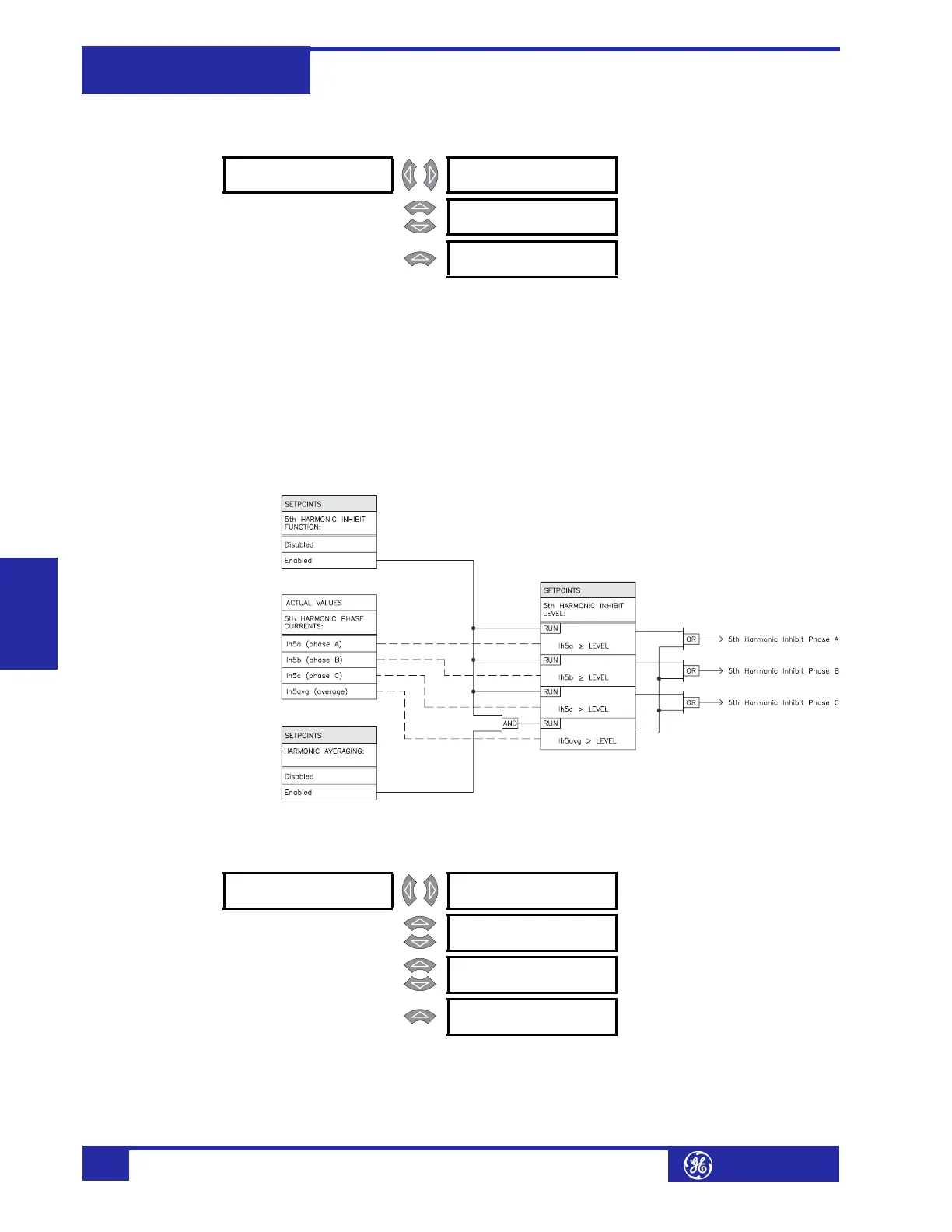
e) 5th Harmonic Inhibit
PATH: SETPOINTS !" S4 ELEMENTS !" DIFFERENTIAL !" 5TH HARM INHIBIT
The 5
th
harmonic inhibit feature of the percent differential element allows inhibiting
the percent differential during intentional overexcitation of the system. This feature
inhibits the percent differential element in a particular phase if the 5
th
harmonic of
the same phase exceeds the harmonic inhibit level setting. With harmonic averaging
enabled, all three phases are inhibited if the three-phase average of the 5
th
harmonic exceeds the level setting.
• HARMONIC AVERAGING: Select “Enabled” to use the three-phase average of
the 5th harmonic current against the harmonic inhibit setting.
• 5th HARMONIC INHIBIT LEVEL: Enter the level of 5th harmonic current
above which the percent differential element will be inhibited from operating.
FIGURE 5–12: 5th Harmonic Inhibit Scheme Logic
Instantaneous Differential
PATH: SETPOINTS !" S4 ELEMENTS !" INST DIFFERENTIAL
This section contains the settings to configure the (unrestrained) instantaneous
differential element, for protection under high magnitude internal faults.
! 5th HARM [!]
INHIBIT
5th HARMONIC INHIBIT
FUNCTION: Enabled
Range: Enabled, Disabled
MESSAGE
HARMONIC AVERAGING:
Disabled
Range: 0.10 to 0.50 x CT in steps of
0.01
MESSAGE
5th HARMONIC INHIBIT
LEVEL: 10.0% fo
Range: 0.1 to 65.0% f
0
in steps of 0.1
! INST [!]
DIFFERENTIAL
INST DIFFERENTIAL
FUNCTION: Enabled
Range: Enabled, Disabled
MESSAGE
INST DIFFERENTIAL
TARGET: Latched
Range: Self-Reset, Latched, None
MESSAGE
INST DIFFERENTIAL
PICKUP: 8.00 x CT
Range: 3.00 to 20.00
×
CT in steps of
0.01
MESSAGE
INST DIFFERENTIAL
BLOCK: Disabled
Range: Logc Inpt 1 to 16, Virt Inpt 1 to
16, Output Rly 2 to 8, SelfTest
Rly, Vir Outpt 1 to 5, Disabled
 Loading...


