S4 Elements
745
Transformer Management Relay
Setpoints
http://www.GEindustrial.com/multilin
5–47
GE Multilin
VOLTAGE is “Enabled”). This setpoint is displayed only if S2 SYSTEM SETUP "#
VOLTAGE INPUT " VOLTAGE SENSING is “Enabled”.
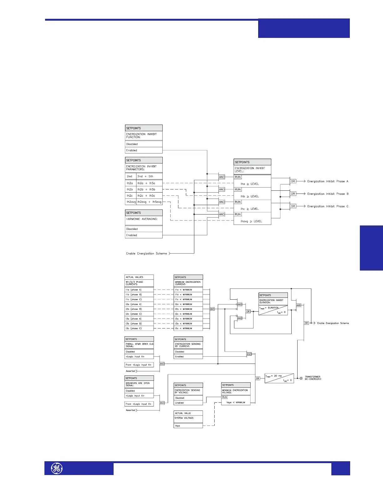
• BREAKERS ARE OPEN SIGNAL: Select any logic input which, when asserted,
indicates to the 745 that the transformer is de-energized. The selected logic
input should be connected to the auxiliary contacts of the transformer breaker
or disconnect switch.
• PARALL XFMR BRKR CLS SIGNAL: Select any logic input which, when
asserted, will indicate to the 745 the onset of sympathetic inrush. The selected
logic input should be connected to the close command going to the parallel
transformer switching device.
FIGURE 5–10: Energization Inhibit Scheme Logic
FIGURE 5–11: Energization Sensing Scheme Logic
 Loading...


