S4 Elements
745
Transformer Management Relay
Setpoints
http://www.GEindustrial.com/multilin
5–41
GE Multilin
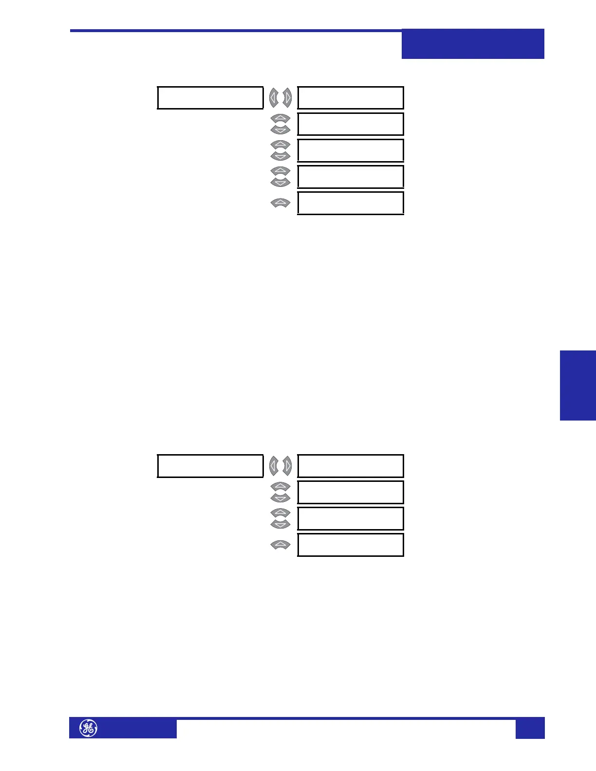
Setpoint Group PATH: SETPOINTS !" S4 ELEMENTS ! SETPOINT GROUP
Each protection and monitoring element setpoint (programmed in S4 ELEMENTS) has
four copies, and these settings are organized in four setpoint groups. Only one
group of settings are active in the protection scheme at a time. The active group can
be selected using the
ACTIVE SETPOINT GROUP setpoint or using a logic input. The
setpoints in any group can be viewed or edited using the
EDIT SETPOINT GROUP
setpoint.
• ACTIVE SETPOINT GROUP: Select the number of the
SETPOINT GROUP whose
settings are to be active in the protection scheme. This selection will be
overridden if a higher number setpoint group is activated using logic inputs.
• EDIT SETPOINT GROUP: Select the number of the
SETPOINT GROUP whose
settings are to be viewed and/or edited via the front panel keypad or any of the
communication ports. Selecting “Active Group” selects the currently active
setpoint group for editing.
• GROUP 2(4) ACTIVATE SIGNAL: Select any logic input which, when
asserted, will (remotely) select
SETPOINT GROUP 2(4) to be the active group. This
selection will be overridden if a higher number setpoint group is activated using
the
ACTIVE SETPOINT GROUP setpoint or another logic input.
Differential Element a) Main Menu
PATH: SETPOINTS !" S4 ELEMENTS !" DIFFERENTIAL
This section contains the settings to configure the percent differential element,
including all associated harmonic inhibit features. The 745 provides three
independent harmonic inhibit features:
HARMONIC INHIBIT, which implements an
inhibit scheme based on 2nd or 2nd + 5th harmonic which is ‘in-circuit’ at all times;
ENERGIZATION INHIBIT, which allows changing the characteristics of the inhibit scheme
during energization to improve reliability; and
5TH HARM INHIBIT, which implements
an inhibit scheme based on 5th harmonic only, allowing inhibiting the percent
differential during intentional overexcitation of the system.
! SETPOINT GROUP [!] ACTIVE SETPOINT
GROUP: Group 1
Range: Group 1, Group 2, Group 3,
Group 4
MESSAGE
EDIT SETPOINT
GROUP: Active Group
Range: Group 1, Group 2, Group 3,
Group 4, Active Group
MESSAGE
GROUP 2 ACTIVATE
SIGNAL: Disabled
Range: Logic Input 1 to 16, Disabled
MESSAGE
GROUP 3 ACTIVATE
SIGNAL: Disabled
Range: Logic Input 1 to 16, Disabled
MESSAGE
GROUP 4 ACTIVATE
SIGNAL: Disabled
Range: Logic Input 1 to 16, Disabled
! DIFFERENTIAL [!] ! PERCENT [!]
DIFFERENTIAL
See page 5–42.
MESSAGE
! HARMONIC [!]
INHIBIT
See page 5–44.
MESSAGE
! ENERGIZATION [!]
INHIBIT
See page 5–45.
MESSAGE
! 5th HARM [!]
INHIBIT
See page 5–48.
 Loading...


