S4 Elements745
Transformer Management Relay
Setpoints
http://www.GEindustrial.com/multilin
5–44
GE Multilin
1. PERCENT DIFFERENTIAL SLOPE 2 is set above 100%.
2. The source is connected to one winding only.
Therefore, the
PERCENT DIFFERENTIAL SLOPE 2 value cannot be greater than 100%. To
increase dependability, the Slope 2 settings should be less than 98%
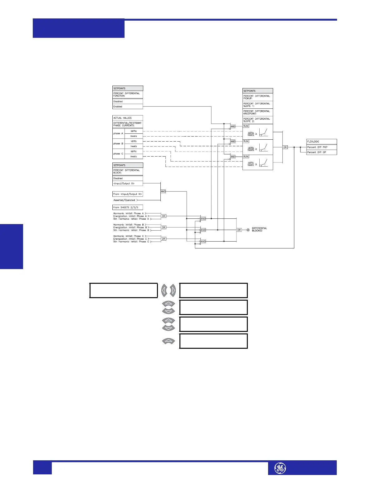
FIGURE 5–8: Percent Differential Scheme Logic
c) Harmonic Inhibit
PATH: SETPOINTS !" S4 ELEMENTS !" DIFFERENTIAL !" HARMONIC INHIBIT
This menu contains the percent differential harmonic inhibit settings. This is the
percent differential element in a particular phase if the 2
nd
harmonic of the same
phase exceeds the
HARMONIC INHIBIT LEVEL setpoint. With harmonic inhibit
parameters set to “2nd + 5th”, the RMS sum of the 2
nd
and 5
th
harmonic
components is compared against the level setting. With harmonic averaging
enabled, all three phases are inhibited if the 3-phase average of the harmonics
exceeds the level setting
• HARMONIC INHIBIT PARAMETERS: Select “2nd” to compare only the 2
nd
harmonic current against the HARMONIC INHIBIT LEVEL. Select “2nd + 5th” to use
the RMS sum of the 2
nd
and 5
th
harmonic components. For most transformers,
the 2
nd
harmonic current alone will exceed 20% during energization and the
“2nd” value is sufficient to inhibit the differential element for inrush current.
! HARMONIC [!]
INHIBIT
HARMONIC INHIBIT
FUNCTION: Enabled
Range: Enabled, Disabled
MESSAGE
HARMONIC INHIBIT
PARAMETERS: 2nd
Range: 2nd, 2nd + 5th
MESSAGE
HARMONIC AVERAGING:
Disabled
Range: Enabled, Disabled
MESSAGE
HARMONIC INHIBIT
LEVEL: 20.0% f0
Range: 0.1 to 65.0% f
0
in steps of 0.1
 Loading...


