S4 Elements
745
Transformer Management Relay
Setpoints
http://www.GEindustrial.com/multilin
5–45
GE Multilin
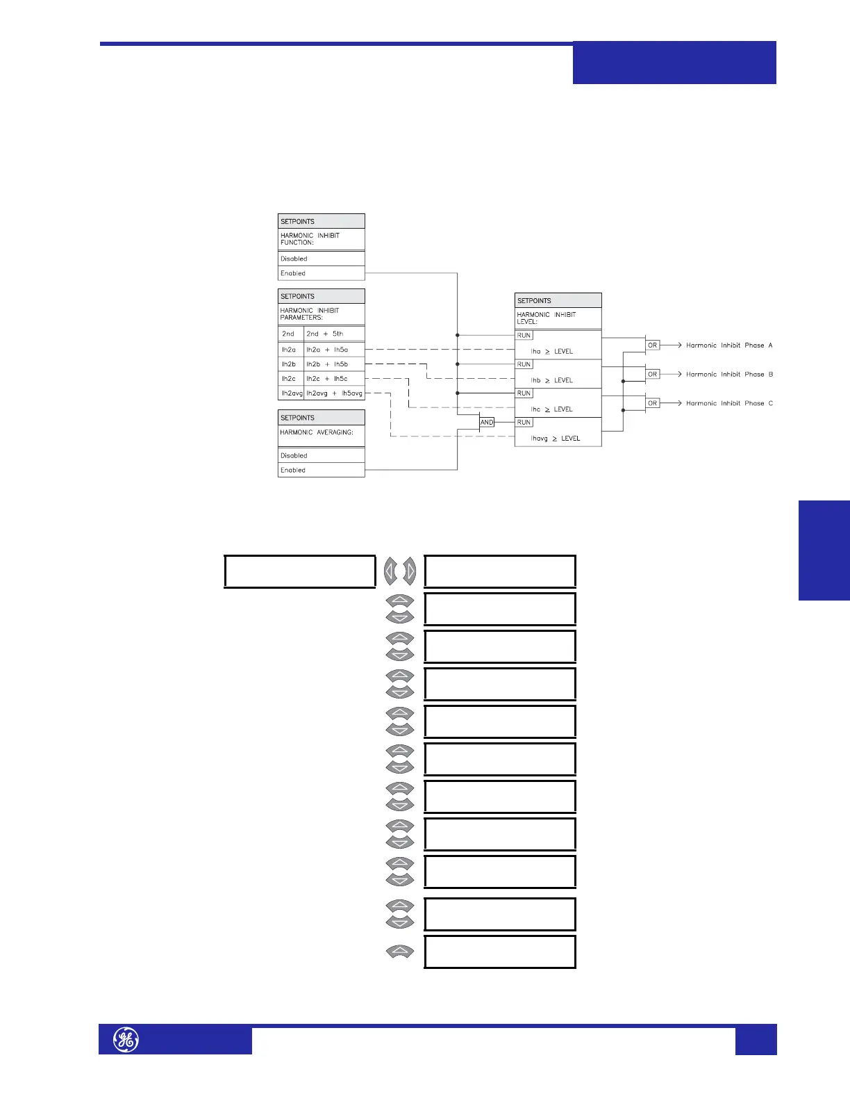
• HARMONIC AVERAGING: Select “Enabled” to use the three-phase average of
the harmonic current against the harmonic inhibit setting. For most
applications, enabling harmonic averaging is not recommended.
• HARMONIC INHIBIT LEVEL: Enter the level of harmonic current (2
nd
or
2
nd
+5
th
) above which the percent differential element will be inhibited from
operating. For most applications, this level should be set to “20%”.
FIGURE 5–9: Harmonic Inhibit Scheme Logic
d) Energization Inhibit
PATH: SETPOINTS !" S4 ELEMENTS !" DIFFERENTIAL !" ENERGIZATION INHIBIT
! ENERGIZATION [!]
INHIBIT
ENERGIZATION INHIBIT
FUNCTION: Enabled
Range: Enabled, Disabled
MESSAGE
ENERGIZATION INHIBIT
PARAMETERS: 2nd
Range: 2nd, 2nd + 5th
MESSAGE
HARMONIC AVERAGING:
Enabled
Range: Enabled, Disabled
MESSAGE
ENERGIZATION INHIBIT
LEVEL: 20.0% f0
Range: 0.1 to 65.0% f
0
in steps of 0.1
MESSAGE
ENERGIZATION INHIBIT
DURATION: 0.10 s
Range: 0.05 to 600.00 s in steps of 0.01
MESSAGE
ENERGIZATION SENSING
BY CURRENT: Enabled
Range: Enabled, Disabled
MESSAGE
MINIMUM ENERGIZATION
CURRENT: 0.10 x CT
Range: 0.10 to 0.50 x CT in steps of
0.01
MESSAGE
ENERGIZATION SENSING
BY VOLTAGE: Disabled
Range: Enabled, Disabled. Seen only if
Voltage Sensing is enabled.
MESSAGE
MINIMUM ENERGIZATION
VOLTAGE: 0.85 x VT
Range: 0.50 to 0.99 x VT in steps of
0.01. Seen only if Voltage
Sensing is enabled.
MESSAGE
BREAKERS ARE OPEN
SIGNAL: Disabled
Range: Logic Input 1 to 16, Disabled
MESSAGE
PARALL XFMR BRKR CLS
SIGNAL: Disabled
Range: Logic Input 1 to 16, Disabled
 Loading...


