Typical Wiring
745
Transformer Management Relay
Installation
http://www.GEindustrial.com/multilin
3–9
GE Multilin
Phase Sequence and
Transformer Polarity
For the correct operation of many relay features, the phase sequence and
instrument transformer polarities shown on the typical wiring diagram must be
followed. Note the markings shown with all instrument transformer connections.
When the connections adhere to this drawing, the relay will operate properly.
AC Current Transformer
Inputs
The 745 has eight or eleven channels for AC current inputs, each with an isolating
transformer and an automatic shorting mechanism that acts when the relay is
withdrawn from its case. There are no internal ground connections on the current
inputs. Current transformers with 1 to 50000 A primaries may be used.
The 745 contains either two or three groups of three phase inputs (specified at the
time of ordering) for the corresponding two or three transformer winding, as well as
two ground current inputs, G1/2 and G2/3. Refer to the wiring diagrams on pages
3–7 and 3–8 for details. Upon transformer type selection, the ground inputs are
associated to one or another winding under the following conditions:
1. The ground input settings will not be shown in the winding configuration if the
winding connection type is Delta.
2. The G1/2 ground input is associated with the first Wye or Zig-Zag type winding
from a two-winding transformer; it is never associated with Winding 3 from a
three-winding transformer setup.
3. The G2/3 ground input is associated with the second Wye or Zig-Zag type wind-
ing from two- or three-winding setup; it is never associated with Winding 1. The
G2/3 ground input is associated with Winding 3 only if Winding 3 is the winding
of the Wye or Zig-Zag connection type from the transformer setup.
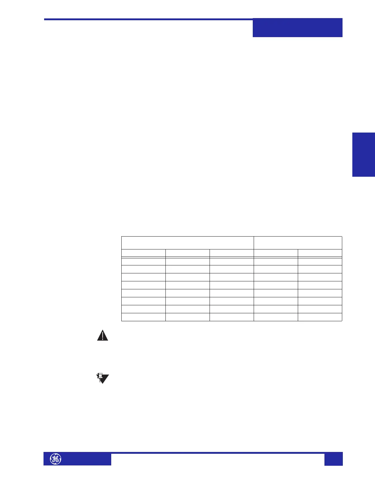
The following table shows the ground inputs use for some typical transformer
setups:
Verify that the relay’s nominal current of 1 A or 5 A matches the secondary
rating of the connected CTs. Unmatched CTs may result in equipment
damage or inadequate protection.
The exact placement of a zero-sequence CT so that ground fault current will be
detected is shown below. Twisted pair cabling on the zero-sequence CT is
recommended.
IMPORTANT: The relay will correctly measure up to 46 times the current
input nominal rating. Time overcurrent curves become horizontal lines for
currents above the 46 × CT rating.
Table 3–2: Typical Ground Input Connections
Transformer Winding Connections Winding Associated with
Ground Input
Winding 1 Winding 2 Winding 3 G1/2 G2/3
Wye Delta -- Winding 1 --
Wye Wye -- Winding 1 Winding 2
Delta Wye -- Winding 2 --
Wye Delta Delta Winding 1 --
Wye Wye Delta Winding 1 Winding 2
Wye Delta Wye Winding 1 Winding 3
Delta Wye Wye Winding 2 Winding 3
Delta Delta Wye -- Winding 3
CAUTION
NOTE
 Loading...


