S4 Elements
745
Transformer Management Relay
Setpoints
http://www.GEindustrial.com/multilin
5–67
GE Multilin
that may lead to a complete collapse. The 745 provides a means of automatically
disconnecting sufficient load to restore an acceptable balance between load and
generation.
The 745 uses both frequency and frequency rate-of-change as the basis for its
operating criteria. These measured values are based on the voltage input or, if
voltage is disabled, the Winding 1 Phase A current input. The relay has two (2)
underfrequency and four (4) rate-of-change levels. Thus, four or more separate
blocks of load can be shed, according to the severity of the disturbance.
In addition to these elements, the 745 has an overfrequency element. A significant
overfrequency condition, likely caused by a breaker opening and disconnecting load
from a particular generation location, can be detected and used to quickly ramp the
turbine speed back to normal. If this is not done, the overspeed can lead to a
turbine trip which would require a turbine start up before restoring the system. If
the turbine speed can be controlled successfully, system restoration can be much
quicker. The overfrequency element of the 745 can be used for this purpose at a
generating location.
We strongly recommend the use of either the voltage, current, or both,
signals for supervision. If no supervising conditions are enabled, the
element could produce undesirable operation!
b) Underfrequency
PATH: SETPOINTS !" S4 ELEMENTS !" FREQUENCY ! UNDERFREQUENCY 1(2)
• MINIMUM OPERATING CURRENT: Enter the minimum value of Winding 1
Phase A current (in units of relay nominal current) required to allow the
underfrequency element to operate.
• MINIMUM OPERATING VOLTAGE: Enter the minimum value of voltage (in
units of relay nominal voltage) required to allow the underfrequency element to
operate.
• UNDERFREQUENCY 1(2) PICKUP: Enter the frequency (in Hz) below which
the Underfrequency 1 element will pickup and start the delay timer.
• UNDERFREQUENCY 1(2) DELAY: Enter the time the frequency remains below
the pickup level before element operation.
NOTE
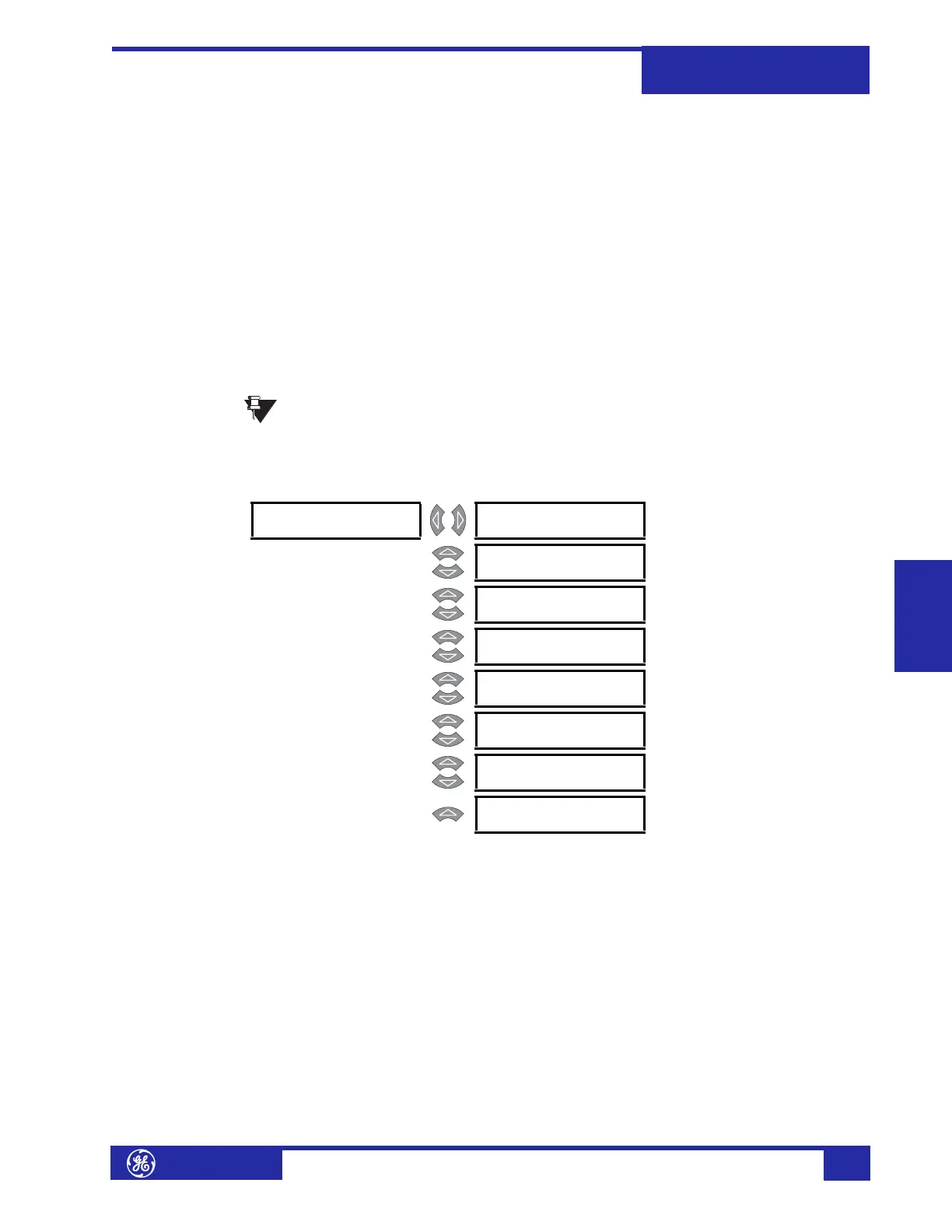
! UNDERFREQUENCY [!]
1
UNDERFREQUENCY 1
FUNCTION: Disabled
Range: Enabled, Disabled
MESSAGE
UNDERFREQUENCY 1
TARGET: Self-Reset
Range: Self-Reset, Latched, None
MESSAGE
CURRENT SENSING:
Enabled
Range: Enabled, Disabled
MESSAGE
MINIMUM OPERATING
CURRENT: 0.20 x CT
Range: 0.20 to 1.00 x CT in steps of
0.01
MESSAGE
MINIMUM OPERATING
VOLTAGE: 0.50 x VT
Range: 0.10 to 0.99 x CT in steps of
0.01
MESSAGE
UNDERFREQUENCY 1
PICKUP: 59.00 Hz
Range: 45.00 to 59.99 Hz in steps of
0.01
MESSAGE
UNDERFREQUENCY 1
DELAY: 1.00 s
Range: 0.00 to 600.00 s in steps of 0.01
MESSAGE
UNDERFREQUENCY 1
BLOCK: Disabled
Range: Logc Inpt 1 to 16, Virt Inpt 1 to
16, Output Rly 2 to 8, SelfTest
Rly, Vir Outpt 1 to 5, Disabled
 Loading...


