Power Break
®
Circuit Breakers
Chapter 2. Breaker Operation
5
charge as soon as the breaker is opened, whether from a
fault trip or from being intentionally opened.
CC
CC
AA
AA
UU
UU
TT
TT
II
II
OO
OO
NN
NN
::
::
Do not wire breakers for both automatic
charge and automatic close unless a bell alarm with
overcurrent lockout is incorporated. Otherwise, the
breaker may repeatedly close into an overcurrent fault.
CC
CC
AA
AA
UU
UU
TT
TT
II
II
OO
OO
NN
NN
::
::
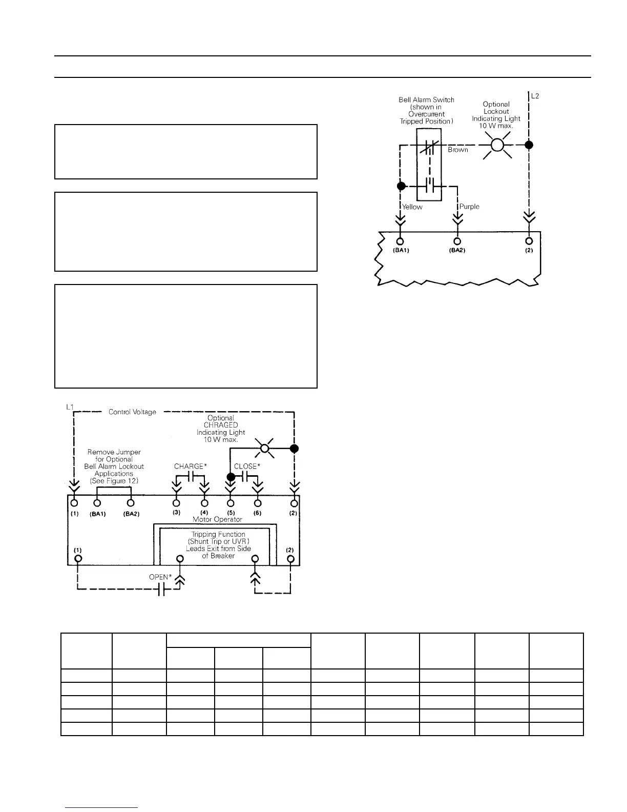
The bell alarm lockout and undervoltage
release both hold the breaker latch open when activated.
To prevent continuous cycling (see Application Notes)
when the breaker is wired for automatic charging, inter-
connect the bell alarm switch to the motor operator ter-
minal board as shown in Figures 7 and 8.
NN
NN
OO
OO
TT
TT
EE
EE
::
::
The motor operator contains a feature that shuts
off control power if the OFF button is held depressed.
Thus, electrical operation is prevented if a key interlock
or padlock accessory is applied in the breaker OPEN con-
dition. If the breaker is equipped with a draw-out inter-
lock (TPDO-1), electrical operation is permitted only if
the draw-out carriage is in the ENGAGED or TEST posi-
tion.
Figure 7. Bell alarm wiring to prevent continuous cycling of the
automatic charging mechanism.
Figure 8. Wiring for optional bell alarm lockout applications.
Wiring Notes
Observe the following notes when wiring the breaker for
operation:
• Customer-supplied contacts (such as CHARGE and
CLOSE) should be momentary action, rated for 0.25
A at 125 Vdc for dc motor operators or rated for 3 A
at 120 Vac for ac motor operators.
• Do not apply power to any terminal board point
other than points 1 and 2.
• Observe the proper polarity for dc motor operators
(point 1 is positive).
• When performing hi-pot or dielectric tests:
– Remove all power leads, both control and power.
– Short all motor operator terminal board points.
– Open the circuit breaker.
– Test between the motor operator terminal board
points and the load side of the breaker’s center
pole (this pole is connected to the frame).
– Test at 2200 Vac for one minute using a current-
limited, nondestructive ac hi-pot tester with
maximum output of 20 mA.
O
eratin
Motor Current, A
Close Nominal Maximum Maximum
Rated
Voltage
Voltage
Range
Locked
Rotor
Full
Load Average
Solenoid,
peak A
Fuses (Slo
Blo 125 V)
Charge
Time , s
Close
Time, s
Opening
Time, s
120 Vac 102–132 8 2.5 1.5 3.0 2 A 5.0 0.83 0.05
125 Vdc 100–140 10 2.5 1.5 3.5 2 A 6.0 0.83 0.05
72 Vdc 57–81 13 3.0 2.0 5.0 3 A 6.0 0.83 0.05
48 Vdc 38–58 20 5.0 2.5 6.6 4 A 6.0 0.83 0.05
24 Vdc 19–29 24 7.0 3.0 13.2 6.25 A 7.5 0.83 0.05
Table 3. Application data for control power.
 Loading...