Power Break
®
Circuit Breakers
Chapter 2. Breaker Operation
3
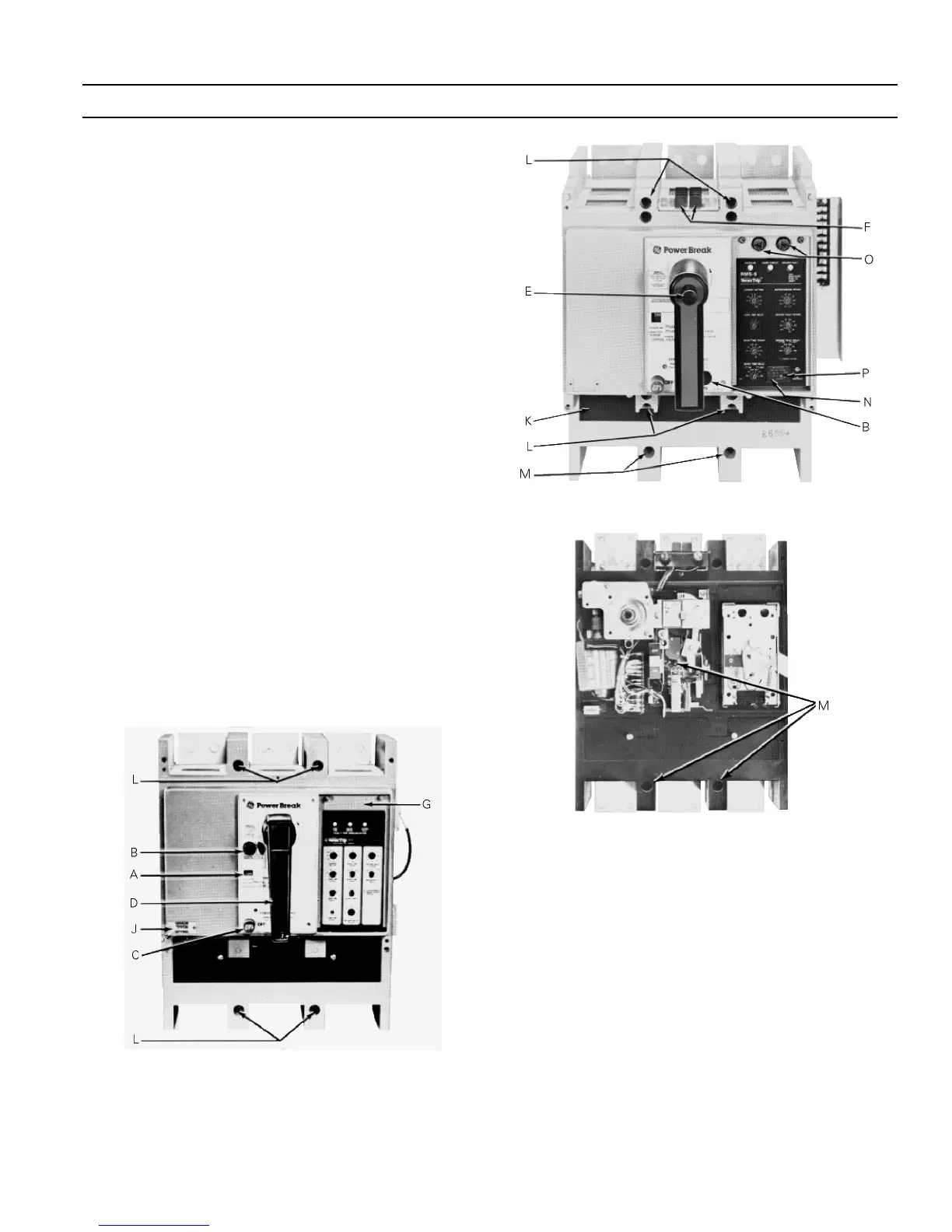
2–1 Standard Features
Power Break circuit breakers are equipped with the follow-
ing standard features. The letters are keyed to the breaker
illustrations in Figures 4, 5, and 6.
AA
AA
Indicator ON – Red
CHG (manual) – yellow
CHARGED (electrical) – yellow
OFF – Green
BB
BB
ON button
CC
CC
OFF button
DD
DD
Manual charging handle
EE
EE
Lockable manual charge engagement button (motor
operated only)
FF
FF
Terminal board (motor operator drive unit)
GG
GG
Removable protective window
JJ
JJ
CT tap setting indicator (MicroVersaTrip only)
KK
KK
Removal protective trip unit cover (Magnetrip™
only)
LL
LL
Cover mounting screws (four)
MM
MM
Midcover mounting screws (three – motor operated
only)
NN
NN
MicroVersaTrip RMS-9 trip unit interchangeable rat-
ing plug
OO
OO
Motor operator control circuit fuses
PP
PP
MicroVersaTrip RMS-9 test set connection port
Figure 4. Manually charged breaker.
Figure 5. Motor operator-charged breaker.
Figure 6. Motor operator charged breaker with the top cover
removed.
2–2 Operating Instructions
Sequence of Operations
The sequence of operations that may be performed on the
circuit breaker is listed in Table 3.
 Loading...