Power Break
®
Circuit Breakers
Chapter 3. Accessories
12
55
55
..
..
Position the charging handle at the home position (6
o’clock) on the outer cover. Align the outer cover-
mounting screw holes with those on the inner cover
and install the four cover-mounting screws. Tighten
to 50–60 in-lbs.
NN
NN
OO
OO
TT
TT
EE
EE
::
::
Ensure that the control terminal board properly
engages the cover retaining slots.
66
66
..
..
Connect the control and power wiring as per the
instructions supplied with the circuit breaker.
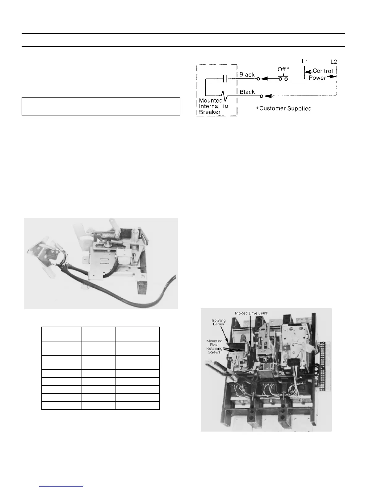
3–3 Shunt Trip Device
The shunt trip, shown in Figure 22, allows the breaker to
be tripped electrically from a remote location. A cut-off
switch is supplied as part of the shunt trip to automatically
remove power from the shunt trip coil when the breaker is
tripped. The electrical characteristics of the shunt trip are
listed in Table 5. Figure 23 is the shunt trip wiring dia-
gram.
Figure 22. Shunt trip device with cut-off switch.
Catalog No.
Voltage
Rating
Max. Inrush
Current, A
TPST 12S
120 Vac
240 Vac
2.25
4.50
TPST13S
480 Vac
600 Vac
1.64
2.05
TPST7S 12 Vdc 4.00
TPST8S 24 Vdc 2.18
TPST9S 48 Vdc 1.09
TPST10S 125 Vdc 1.00
TPST11S 250 Vdc 0.21
Table 5. Shunt Trip electrical characteristics.
Figure 23. Shunt trip wiring diagram.
Mounting Plate Removal
The mounting plate is used as the anchor position for the
shunt trip, blown-fuse trip, and undervoltage release
accessories. Breakers are shipped from the factory with
either a mounting plate or an L-shaped bracket to retain
the molded-plastic crank. A new mounting plate is pro-
vided in the shunt trip kit, blown-fuse trip kit, undervol-
tage release kit, and auxiliary switch kit.
• If the breaker was supplied with an L-shaped bracket,
remove the two retaining screws, discard the bracket,
and skip to the appropriate installation instructions.
• If the breaker was supplied with a mounting plate,
remove it with the following procedure:
11
11
..
..
Remove the three mounting plate retaining screws
and the isolation barrier, shown in Figure 24.
22
22
..
..
Lift out the accessory mounting plate and remove the
molded drive crank.
33
33
..
..
If a tap changer was supplied, remove the two screws
from the phenolic block before removing the mount-
ing plate.
Figure 24. Locations of the mounting plate retaining screws, isolation
barrier, and molded drive crank.
 Loading...