Power Break
®
Circuit Breakers
Chapter 3. Accessories
14
3–4 Undervoltage Release Device
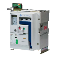
The undervoltage release device (UVR), shown in Figure
28, opens the circuit breaker when the supply voltage
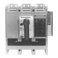
drops to 35–60% of its rated value. Figure 29 shows the
dropping resistor supplied with 240–600 volt UVRs. The
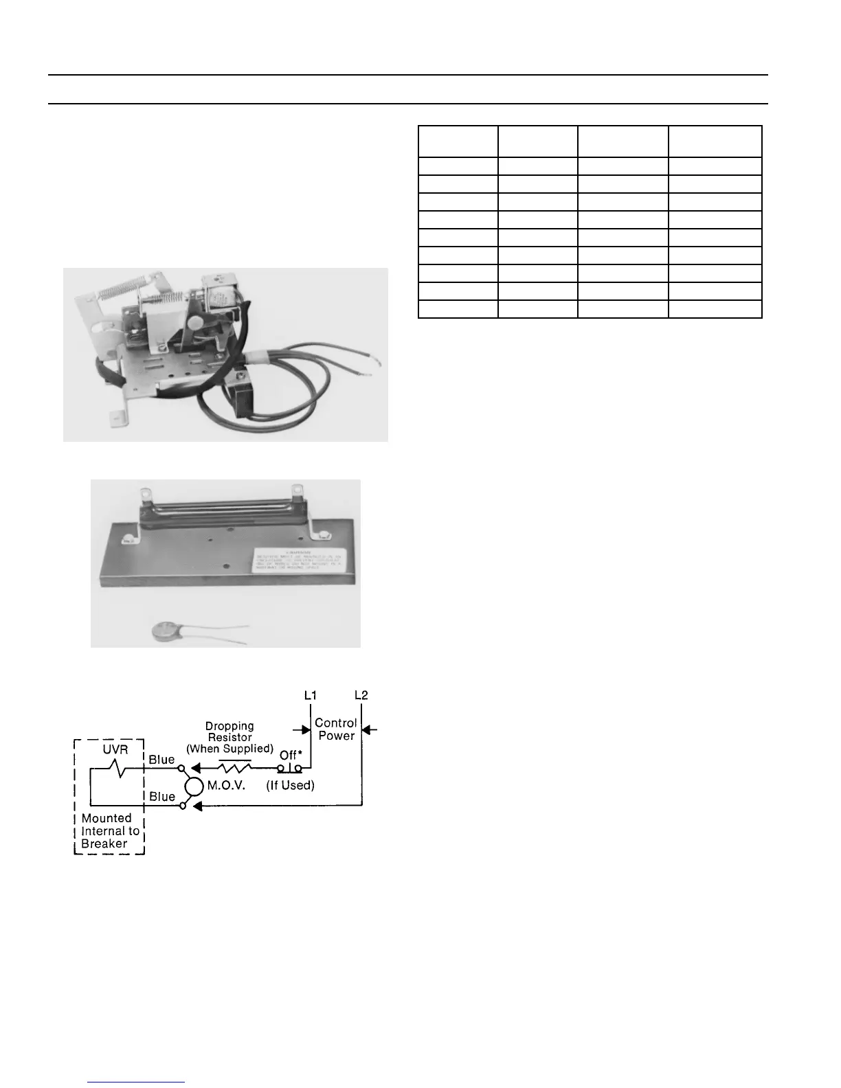
UVR electrical characteristics are listed in Table 6. The
UVR wiring diagram is in Figure 30.
Figure 28. Undervoltage release device.
Figure 29. Dropping resistor supplied with 240–600 V UVRs.
Figure 30. UVR wiring diagram.
Catalog
Number
Voltage
Rating
Continuous
Current, mA
Dropping
Resistor*
TPUV1S 120 Vac 25 none
TPUV2S 240 Vac 25 5000 ?, 25 W
TPUV2S 480 Vac 25 15,000 ?, 50 W
TPUV6S 600 Vac 25 20,000 ?, 50 W
TPUV7S 12 Vdc 211 none
TPUV8S 24 Vdc 104 none
TPUV9S 48 Vdc 54 none
TPUV10S 125 Vdc 24 none
TPUV11S 250 Vdc 24 5000 ?, 25 W
* Ohmite Type 270
Table 6. UVR electrical characteristics.
UVR Installation
11
11
..
..
Remove the circuit breaker cover(s) as described
above in
3–2 Circuit Breaker Cover
.
22
22
..
..
The UVR assembles to a mounting plate. Not all
breakers are shipped from the factory with a mount-
ing plate. Some breakers have only an L-shaped
bracket to retain the molded-plastic crank. A mount-
ing plate is provided in the UVR kit.
• If the breaker is supplied with an L-shaped
bracket, remove the two retaining screws and dis-
card the bracket. Follow the
Mounting Plate
Installation
instructions and continue on to step
3.
• If the breaker is supplied with a mounting plate,
continue with step 3.
33
33
..
..
Remove the slide reset lever spring from the mount-
ing plate, as shown in Figure 31. Be careful not to
nick or damage the spring in any way, since it will be
needed for reassembly.
44
44
..
..
Push the latch and slide reset lever forward to pro-
vide mounting clearance for the UVR assembly.
55
55
..
..
Position the UVR assembly mounting bracket so that
its retaining hole engages the latch pivot post, as
shown in Figure 32.
66
66
..
..
Line up the UVR bracket’s mounting hole with the
tapped hole in the accessory mounting plate. Install
the screw and lock washer, as shown in Figure 33.
Tighten the screw to 9–11 in-lbs.
77
77
..
..
Replace the slide reset lever spring, shown in Figure
31.
88
88
..
..
Remove the knockouts in the side of the base, as
required. Each knockout will accommodate up to
three bundles of wire. Remove all sharp edges with a
file.
99
99
..
..
Remove all debris from the inside of the breaker.
 Loading...