Power Break
®
Circuit Breakers
Chapter 3. Accessories
10
3–1 Introduction
These instructions cover the field installation of internally
mounted electrical accessories. They are UL listed for use
in all 800–2000 A frame Power Break® circuit breakers
with MicroVersaTrip® trip units. These accessories may
also be installed in 800–1600 A frame Power Break break-
ers with MagneTrip™ trip units, but the UL listing is
voided.
The control leads of internally mounted accessories exit in
pigtail form from the side of the breaker. These leads are
terminated at the secondary disconnect points of draw-out
breakers or at optional terminal blocks when specified for
stationary-mounted breakers. All leads are color coded as
listed in Table 4.
Accessory Lead Color
No. of
Leads
Shunt Trip Black 2
Undervoltage
Release
Blue 2
Auxiliary Switch
White – common
Red – OPEN (NO)
Brown/White – CLOSED (NC)
3 per
switch
Bell Alarm
(Overcurrent
Lockout)
Yellow – common
Purple – CLOSED (NC)
Brown – OPEN (NO)
3
Blown-Fuse Trip
(3-Coil Shunt Trip)
Line End Load End Phase
Red Brown-White A
Blue White B
Yellow Black C
6
Closing Solenoid
(Manual Breakers
only)
White – common
Black – remote indication
Orange – remote close
3
Table 4. Accessory lead color codes.
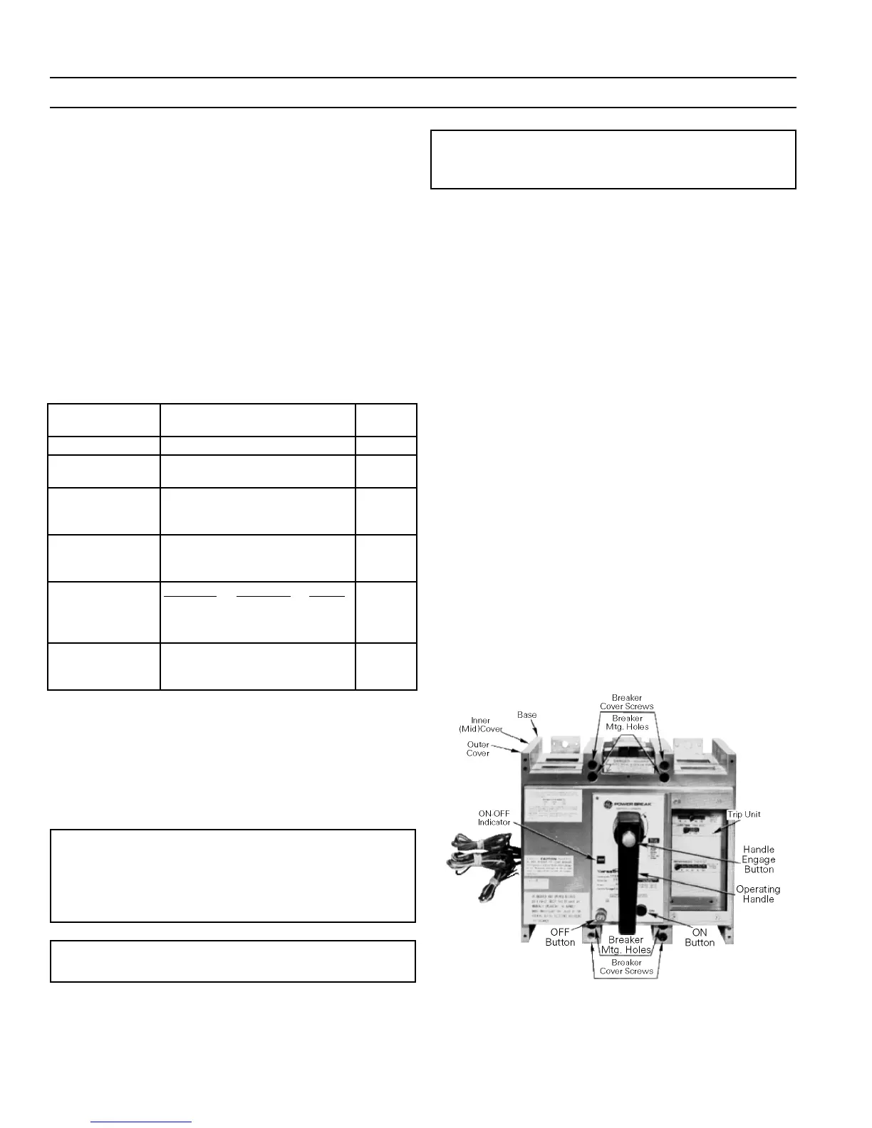
3–2 Circuit Breaker Cover
Before any accessories can be installed in a Power Break
circuit breaker, the cover(s) must be removed, as
described in the following sections.
WW
WW
AA
AA
RR
RR
NN
NN
II
II
NN
NN
GG
GG
::
::
Before installing any accessories, completely
de-energize the circuit breaker and disconnect it from
the electrical circuit. This is mandatory, since the
breaker must be ON during certain stages of installation
and testing.
CC
CC
AA
AA
UU
UU
TT
TT
II
II
OO
OO
NN
NN
::
::
Do not turn the breaker upside down, since
loose parts may become lost.
NN
NN
OO
OO
TT
TT
EE
EE
::
::
All breakers are equipped with mechanical inter-
locks that automatically trip the breaker when the cover
is removed with the breaker closed.
Breaker Cover Removal
Manual Breaker
Use the following procedure to remove the cover of a
manually operated breaker:
11
11
..
..
Press the off button to open the circuit breaker.
22
22
..
..
Remove the four cover-mounting screws.
33
33
..
..
Remove the breaker cover.
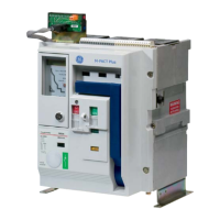
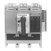
Electrically Operated Breaker
Use the following procedure to remove the cover of an
electrically operated breaker. An 800 A frame breaker is
shown in Figure 17 and a 1600–2000 A frame breaker is
shown in Figure 18.
11
11
..
..
Press the off button to open the circuit breaker.
22
22
..
..
Disconnect all external leads from the terminal
board.
33
33
..
..
Remove the four cover mounting screws.
44
44
..
..
Remove the outer cover.
55
55
..
..
On 1600-2000 A framer breakers only, remove the two
inner-cover mounting screws, as shown in Figure 18.
66
66
..
..
Loosen the captive inner-cover lock screw, as shown
in Figure 19.
77
77
..
..
Remove the inner cover.
Figure 17. 800 A frame electrically operated breaker.
 Loading...