Power Break
®
Circuit Breakers
Chapter 3. Accessories
17
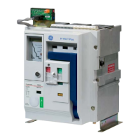
Figure 37. Auxiliary switch wiring diagram.
Catalog
Number
Number of
Switch Elements
Maximum
Current Rating
TPAS2ABx 1–12
6 A at 240 Vac
.25 A at 250 Vdc
.50 A at 125 Vdc
* Replace x with a number from 1–12 for
the number of switch elements.
Table 7. Auxiliary switch electrical characteristics.
Auxiliary Switch Installation
11
11
..
..
Remove the circuit breaker cover(s) as described in
Breaker Cover Removal
.
• If the breaker was supplied with an L-shaped
bracket (see
Mounting Plate Removal
), remove
the two retaining screws, discard the bracket, and
install the mounting plate provided in the kit (see
Mounting Plate Installation
).
22
22
..
..
Both the left and right breaker poles can accept up to
six auxiliary switches. If the left pole contains a shunt
trip, two of the six auxiliary switch positions must be
used for the cut-out switches; thus, only four auxil-
iary switches may be used in the left pole.
33
33
..
..
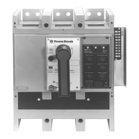
If auxiliary switches are to be installed in the right
pole, remove the trip unit by depressing the lock
release lever while lifting up on the trip unit. Remove
the trip unit mounting plate, shown in Figure 38.
44
44
..
..
Position the auxiliary switch assembly so that the
tapped mounting holes on its bracket line up with
the through holes in the arm stop, as shown in
Figure 39.
55
55
..
..
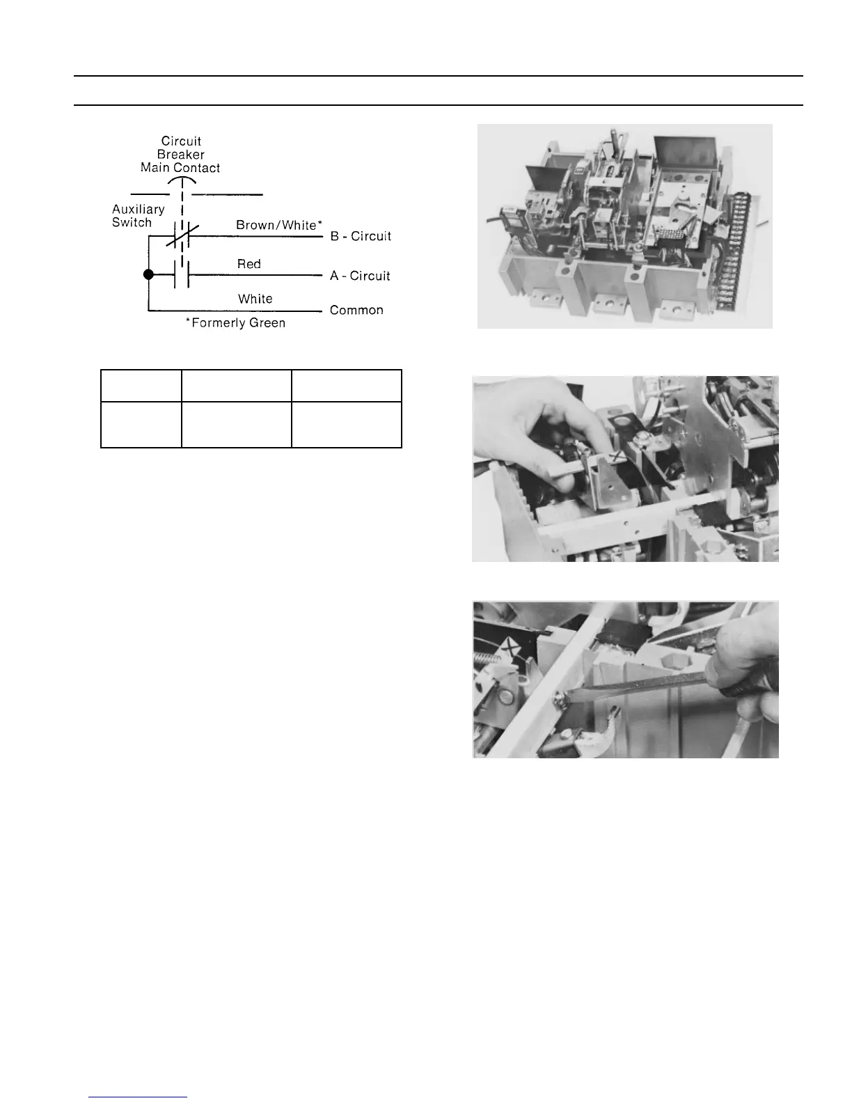
Secure the auxiliary switch assembly to the arm stop
with two #8 ×
9
/16 screws and lock washers, as shown
in Figure 40. Tighten the screws to 23 in-lbs.
Figure 38. Trip unit removed from the breaker.
Figure 39. Installing the auxiliary switch assembly.
Figure 40. Securing the auxiliary switch assembly.
66
66
..
..
Remove knockouts in the side of the base, as
required. Each knockout will accommodate up to
three bundles of wire. Remove all sharp edges with a
file.
77
77
..
..
Use the supplied wire ties to secure the leads as
shown in Figure 20.
88
88
..
..
Replace the trip unit mounting plate and trip unit.
99
99
..
..
Replace the breaker cover(s) as described in
Circuit
Breaker Cover Reassembly
.
11
11
00
00
..
..
Perform the following functional checks:
aa
aa
..
..
With the breaker off, use a continuity tester to
verify continuity between the white and brown-
 Loading...