PROTEUS XR/a
GE MEDICAL SYSTEMS Operator Manual
REV 11 DIRECTION 2259724-100
7-7
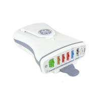
TABLE 7-1
OTS OPERATOR CONTROLS AND INDICATORS
Item Title Type Description
1 kV Display Indicator Display exposure kV.
2 mAs Display Indicator Display exposure mAs.
3 kV Increment and
Decrement Keys
Control Increase or Decrease exposure kV between 40-150. If kV
is over limitation, up or down key will blink.
4 mAs Increment and
Decrement Keys
Control Increase or Decrease exposure mAs between 0.5-630. If
mAs is over limitation, up or down key will blink.
5 Unit Display Indicator Display SID scale (It is set in factory).
6 SID Display Indicator Display SID scale.
7 Angulation Display Indicator Display tube rotation angle.
8 Tube Angulation
Lock Release
Control Releases magnetic lock to allow tube angulation. Normally
open momentary type button, without indicator.
9 Vertical Lock
Release
Control Releases magnetic lock to allow vertical tube motion.
Normally open self-lock type button, with green indicator.
10 All Lock Release Control Releases all OTS magnetic locks to allow vertical,
transverse, longitudinal. Normally open momentary type
button, without indicator.
11 All Lock Release Control Releases all OTS magnetic locks to allow vertical,
transverse, longitudinal. Normally open momentary type
button, without indicator.
12 MANU. COLI Indicator Indicates that the collimator is working in manual mode.
In table Bucky mode: when 75°> |tube angle| >10°,
auto collimator switch to manual collimator.
When |tube angle| >75°, manual collimator switch to auto
collimator and exposure holder lamp is on. SID displays 0.
In Wall Foot mode: when 75° > | tube angle+90 | >10°,
auto collimator switch to manual collimator.
In Wall Head mode: when 75° > | tube angle+90 | >10°,
auto collimator switch to manual collimator. When |tube
angle+90|>75°, manual collimator switch to auto collimator
and exposure holder lamp is on. SID displays 0.
13 Exposure Hold Exposure Indicates for some reason an exposure is not permitted.
(Lateral and longitudinal detent, vertical SID, tube angle, or
cassette)
14 READY Exposure This button is lit when the system is ready for exposure.
15 DETENT Control Lock or Release the Detent magnetic lock. Normally open
self-lock type button.
16 Lateral Lock
Release
Control Release magnetic lock to allow lateral motion. Normally
closed self-lock type button, with green indicator.
17 Longitudinal Lock
Release
Control Release magnetic lock to allow longitudinal motion.
Normally closed self-lock type button, with green indicator.
18 Table Top Receptor Selects the Table Top as the image receptor.
19 TABLE Receptor Selects the table Bucky/cassette tray as the image receptor
20 WALL Receptor Selects the Wall Stand Film Cabinet as the image receptor.
21 TOMO-LINK Receptor Selects the Tomo-link as the image receptor.
22 Switch Key Control Key for X-ray Field Limitation System Failure.
FOR TRAINING PURPOSES ONLY!
NOTE: Once downloaded, this document is UNCONTROLLED, and therefore may not be the latest revision. Always confirm revision status against a validated source (ie CDL).

 Loading...