3.5 INSTALLATION OF A BATTERY EXTENSION PACK
With a battery extension pack you can increase the battery runtime of the UPS. If you do not install a battery extension pack
please skip this section and proceed with 3.6.
NOTE
The battery extension packs are suitable if connectable to circuits directly connected to mains and
compliant with the following:
Nominal Voltage (Vdc): 36 (700 - 1000 VA) / 72 (1500 – 3000 VA)
Nominal Capacity (Ah): 14
Recharge Current (A): 1.5
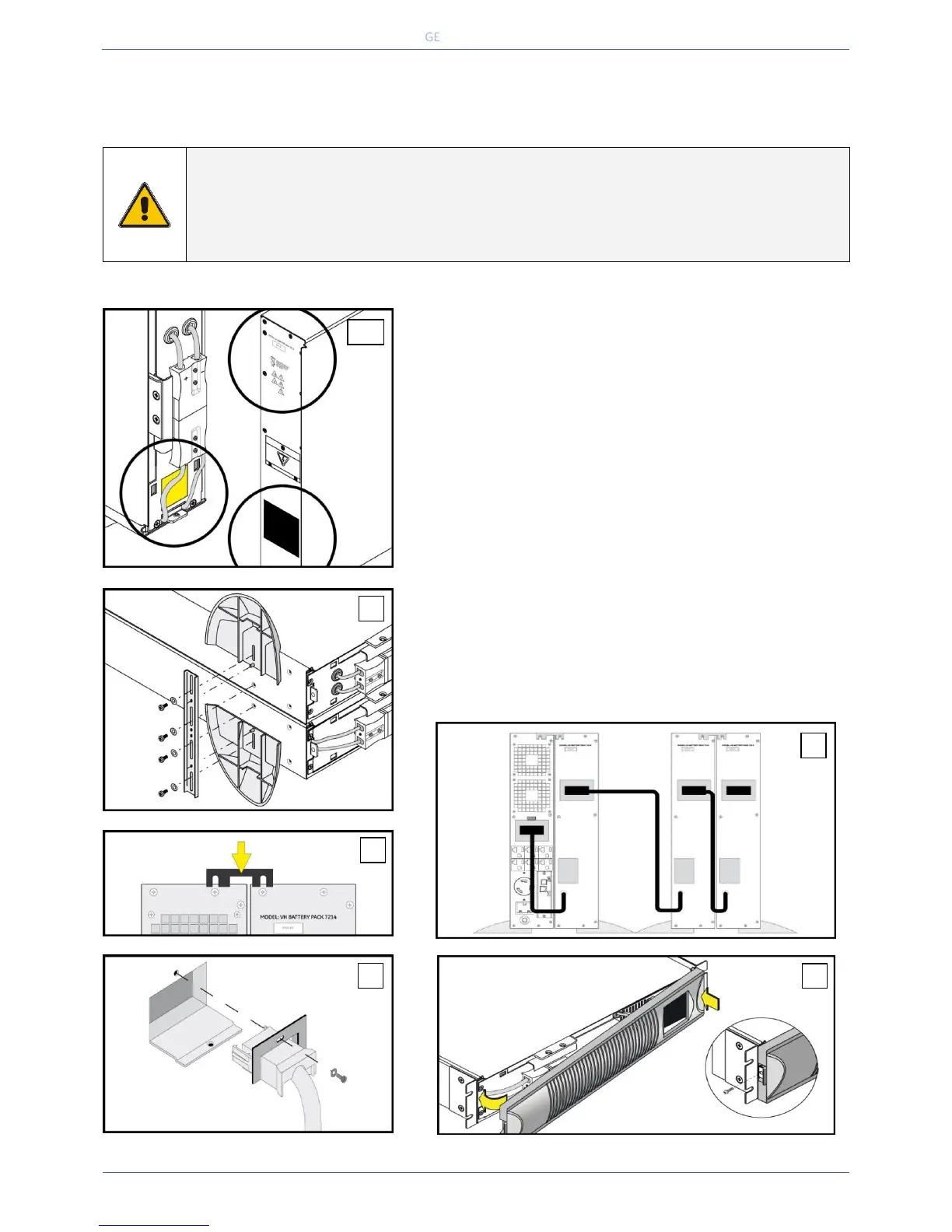
1. Before installation, check whether the nominal voltage of the battery
pack is suitable for the UPS: the voltage mentioned on the label on the
battery drawer of the UPS and the one on the rear panel of the battery
extension pack (36 Vdc or 72 Vdc) should match.
2. Make sure that the battery breaker on the rear side of the battery
pack is in the “OFF” position.
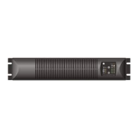
3. UPS and battery pack can be mounted together in one set of
mounting supports (for rack mount see 3.3.2).
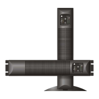
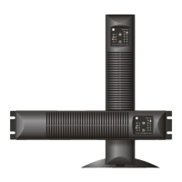
4. At the rear side the UPS and battery pack can be coupled using the
coupling bracket that came with the battery pack.
5. Connect the DC connector of the battery pack to the DC socket of
the UPS (fig. 5a and 5b). You will hear a click when the cable is
properly connected. Block the DC connector: install the small
locking plate that came with the battery pack, and fasten it with
the screw provided.
6. Connect the DC connectors at the front side of the battery pack
similar to UPS (See 3.3.1 step 3).
7. Assemble the front panel: insert the two metal clamps at the rear of
the panel into the holes at the upper side of the UPS, then click the
front panel into position. Fix the front panel with the screw provided.
8. Turn the battery breaker at the rear side of the battery pack into
position “ON” to complete installation.
 Loading...