3.6 CONNECTIONS
3.6.1 Connecting interface devices
.If you do not want to use the communication capabilities of the UPS, please skip this section and proceed with 3.6.2.
The UPS is equipped with two interface ports: a USB port and an RJ11 port, allowing advanced communication between
the UPS and a computer (network). Refer to chapter 5 for more detailed information.
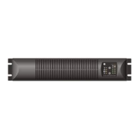
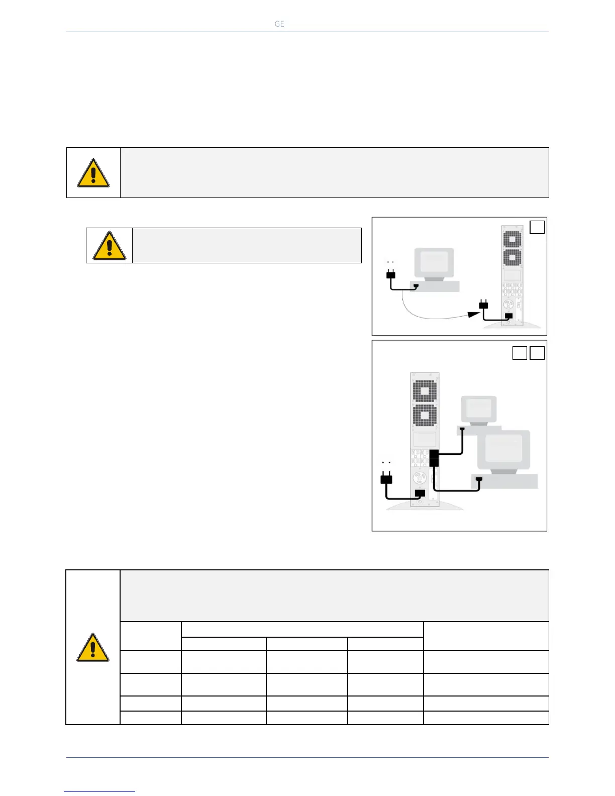
3.6.2 Connecting power and load
2 Disconnect the power cord from the computer (see note below) and
connect this cord to the male input socket (1, fig. 3.4.b) at the rear of
the UPS.
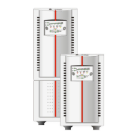
VH3000 UL only: connect the cable to the wall socket (1a, fig. 3.4.a).
3 Add up the power consumption (in VA) of the appliances that will be
protected by the UPS (‘the load’) and make sure that the resulting value
does not exceed the VA output rating of the UPS. This way you ensure
that the UPS is able to supply the required output and prevent that an
overload situation will happen.
4. Using the output cords (see note below) connect the load to the
appliance outlets (3 & 3a, fig. 3.4.a/b) of the unit. Spread the loads over
the appliance outlets as equally as possible. If you use a distribution
box to connect more than one appliance per outlet, please note that
the maximum AC-current ratings of each appliance outlets is 20A, and
30A for the VH3000 UL (3 & 3a, fig. 3.4.a/b).
5 Connect the mains cord of the UPS to a working, grounded AC wall
socket outlet. The green LED ‘operation’ will blink now: mains power is
available and the batteries are charging. If the LED does not blink but
illuminates continuously instead, press keypad ‘0’ for one second.
If both LEDs ‘operation’ and ‘alarm’ blink and the beeper sounds
1/2secs, phase and neutral are reversed at the input of the UPS.
Please read 4.4.13 and take appropriate measures.
For best results, allow the UPS to recharge the batteries during a period
of approx. 2 hours. It is acceptable to use the UPS without first charging
the battery, but the runtime may be reduced.
 Loading...