Configurable serial
line isolated to 1500V
RS422/485 or RS232
Passive current loop
(max. 1200 baud)
(optional
R60 special)
• Serial line
27
26
25
24
-
+
-
+
Tx
Rx
A (Data +)
B (Data -)
RS485 2-wires
GND
RS232
Tx
Rx
• Linear (V)
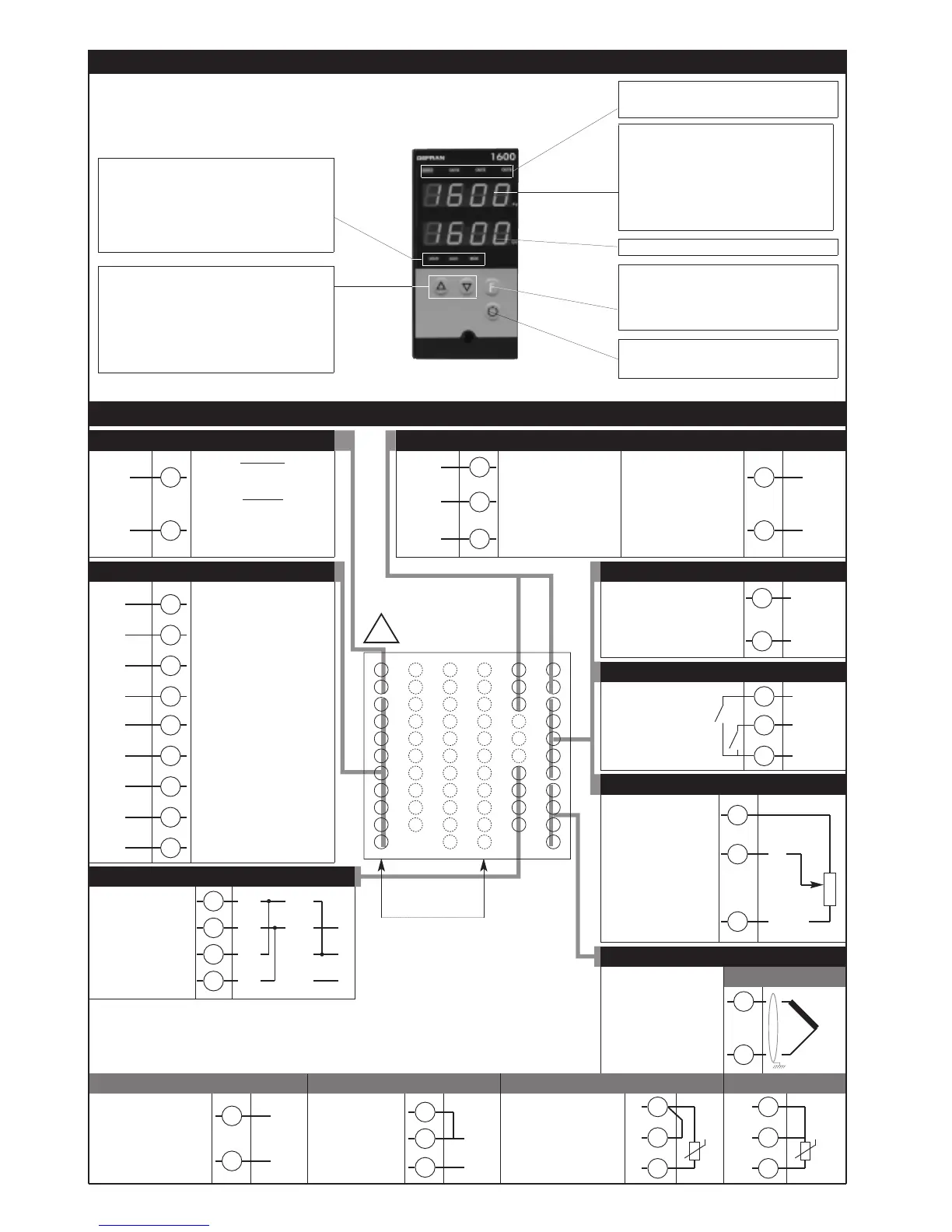
3 • DESCRIPTION OF FACEPLATE
User configurable
generic output
- 5A/250Vac relay, cosϕ=1
- 11Vdc logic,
Rout=220Ω (6V/20mA)
Standard:
100...240Vac/Vdc ±10%
Optional:
20...27Vac/Vdc ±10%
50/60Hz
Digital inputs isolated
1500V
- NPN 24V, 4,5mA
- PNP 24V, 3,6mA
(12V, 1,2mA)
• Digital inputs
4 • CONNECTIONS
• Outputs
+
-
User configurable generic
output
- 5A/250Vac relay, cos
ϕ=1
- 11Vdc logic, Rout=220Ω
(6V/20mA)
Available thermocouples:
J, K, R, S, T, B, E, N,
Ni-Ni18Mo, L NiCr-CuNi
- Observe polarities
- For extensions, use the
correct compensating
cable for the type of TC
used
• Inputs
• TC
2
1
Linear input in dc voltage
0...50mV, 10...50mV,
0...10V, 2...10V
2
1
+
-
8
5
7
14
16
15
17
Out3 (AL1)
IN1
IN2
COM
• Power Supply
12
13
~
~
Auxiliary input isolated
1500V
Current transformer
50mAac; 1,5Ω; 50/60Hz
Remote setpoint
0...20mA, 4...20mA, 5Ω,
0...1V, 0...10V,> 1MΩ
Potentiometer > 500Ω
• Auxiliary input
6
5
~
~
• Outputs
User configurable
generic output
- analogue output
isolated to 1500V
(0 ... 10V, 0 ... 20mA,
4 ... 20mA)
11
10
+
-
Out4
(AL2 / HB)
33
31
0V
+W2
Transmitter supply isolated
1500V
10/24Vdc, max. 30mA
short-circuit protection
9
5
+
-
18
20
19
21
22
Out2 (Close) Out1 (Open)
C
32
+W1
• Transmitter supply
GND
+ Vt
1800 1600
(-) NC
(-) NC
(-) NC
(+) NO
(+) NO
(+) NO
C
C
!
PWR
• Pt100 2 wires o PTC
Use wires of adequate
diameter (min. 1mm
2
)
PT100, JPT100, PTC
• Pt100 3 wires
3
1
2
3
1
2
TT
Linear input in dc
current
0...20mA, 4...20mA
• Linear (I)
4
1
2
-
+
9
Pot
+10V+Vt
GND
PV Display: Indication of process variable
Error Indication: LO, HI, Sbr, Err
LO= the value of process variable is < di LO_S
HI= the value of process variable is > di HI_S
Sbr= faulty sensor or input values higher than max.
limits
Err= PT100 third wire opened for PT100, PTC or
input values lower than min. limits
(i.e.: TC wrong connection)
Automatic/Manual adjustment selection
Active only when PV display visualises the process
variable
Function key
Gives access to the various configuration phases ••
Confirms change of set parameters and browses
next or previous parameter (if Auto/Man key is
pressed)
Function indicators
Indicates modes of operation
MAN = OFF (Automatic control)
MAN = ON (Manual control)
AUX = OFF (IN1 = OFF - local Setpoint 1)
AUX = ON (IN1 = ON - local Setpoint 2)
REM = OFF (local Setpoint)
REM = ON (remote Setpoint)
SV display: Indication of setpoint
Indication of output states
OUT 1 (Open); OUT 2 (Close);
OUT 3 (AL 1); OUT 4 (HB)
“Raise” and “Lower” key
Press to increment (decrement) any numerical
parameter ••
Increment (decrement) speed is proportional to time
key stays pressed ••
The operation is not cyclic: once the maximum
(minimum) value of a field is reached, the value will
not change even if the key remains pressed.
2
80080D_MHW_1600-1800_0308_ENG

 Loading...