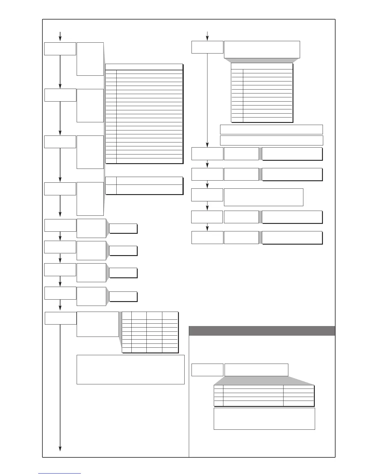
• Prot
an.o.1
l.an.1
x.an.1
an.o.2
l.an.2
x.an.2
rl.o.1
rl.o.2
rl.o.3
rl.o.4
(t.1
(t.2
(t.3
(t.4
rel.
Fault action (sets state in
case of probe fault) Alarm
outputs AL1, AL2, AL3;
Select intrinsic safety
Minimum limit of
analogue repetition
signal output 1
Note:
1) In case of broken probe, logic state of individual alarm assumes
selected logic value without consideration of alarm type (direct or
inverse): ON=alarm active;
OFF=alarm inactive
2) Assign alarms to available outputs by entering codes rLo1, rLo2,
rLo3, rLo4.
Maximum limit of
analogue repetition
signal output 1
Minimum limit of
analogue repetition
signal output 2
Maximum limit of
analogue repetition
signal output 2
An.o.x Reference value
0 PV - process variable
1 SSP - active setpoint
2 SP - local setpoint
3 InP.2 - aux input
4 Deviation (SSP-PV)
5 HEAT (*)
6 COOL (*)
7 AL1 (alarm point)
8 AL2 (alarm point)
9 AL3 (alarm point)
10 AL.HB - (alarm point)
11 Value acquired from serial line
Out W1
Assignment of signal or reference value: PV, SP,
SP-PROG, DEV+, DEV-, IN.AUX, HEAT, COOL,
AL1, AL2, AL3, serial line value
Out W2.
Assignment of signal or reference value: PV, SP,
SP-PROG, DEV+, DEV-, IN.AUX, HEAT, COOL,
AL1, AL2, AL3, serial line value
Out 1
Allocation of
reference signal:
HEAT, COOL,
AL1, AL2, AL3,
repetition of
digital inputs
Cycle time for AL3
relay or logic
output = HEAT or
COOL
67
68
69
70
74
75
76
77
78
79
80
81
_rEL. Alarm Alarm Alarm
123
0 OFF OFF OFF
1 ON OFF OFF
2 OFF ON OFF
3 ON ON OFF
4 OFF OFF ON
5 ON OFF ON
6 OFF ON ON
7ONONON
-100.0...100.0% for power
-1999...9999 for inputs and setpoint
An.o.1, An.o.2
1 ... 200 sec
+ 16 for inverted output with respect to reference value
+ 32 for output with 2...10V, 4...20mA signal
(*) - Fixed scale limits
- Retransmission output not available with ON/OFF control action
71
72
73
Cycle time for
MAIN relay or
logic output =
HEAT or COOL
Cycle time for AL1
relay or logic
output = HEAT or
COOL
Cycle time for AL2
relay or logic
output = HEAT or
COOL
1 ... 200 sec
(0.1 ... 20.0 sec)
1 ... 200 sec
1 ... 200 sec
Out 2
Allocation of
reference signal:
HEAT, COOL,
AL1, AL2, AL3,
repetition of
digital inputs
Out 3
Allocation of
reference signal:
HEAT, COOL,
AL1, AL2, AL3,
repetition of
digital inputs
Out 4
Allocation of
reference signal:
HEAT, COOL,
AL1, AL2, AL3,
repetition of
digital inputs
-100.0...100.0% for power
-1999...9999 for inputs and setpoint
-100.0...100.0% for power
-1999...9999 for inputs and setpoint
-100.0...100.0% for power
-1999...9999 for inputs and setpoint
rL.o.1, rL.o.2, rL.o.3, rL.o.4
+ 32 for inverse logic signal output
rL.o.x Function of main output relay/logic (OUT1)
0 HEAT (control output for heating)
1 COOL (control output for cooling)
2 AL1 - alarm 1
3 AL2 - alarm 2
4 AL3 - alarm 3
5 AL.HB - alarm HB
6 LBA - alarm LBA
7 IN1 - repetition of logic input 1
8 IN2 - repetition of logic input 2
9-
10 -
11 -
12 Repeat Timer
13 Repeat Set / Reset
14 (AL1) OR (AL2)
15 (AL1) OR (AL2) OR (AL3)
16 (AL1) AND (AL2)
17 (AL1) AND (AL2) AND (AL3)
18 (HBAL) OR (AL1)
19 (HBAL) OR (AL1) OR (AL2)
20 (HBAL) AND (AL1)
21 (HBAL) AND (AL1) AND (AL2)
64 Heat control output with
fast cycle time (*)
65 Cool control output with
fast cycle time (*)
(*) only for rL.o.1.; HB alarm is disabled if
associated with Out1 output
Prot
42
Protection code
Prot Display Modification
0 SP, InP2, alarms, OutP, INFO, DATA SP, alarms, DATA
1 SP, InP2, alarms, OutP, INFO, DATA SP, alarms
2 SP, InP2, alarms, OutP, INFO SP
3SP
+ 4 to disable InP, Out
+ 8 to disable CFG, Ser,
+ 16 to disable SW “power-up - power down”
+ 32 disable manual power latching
+ 64 to disable manual power modification
-
-
-
-
-
7
80080D_MHW_1600-1800_0308_ENG

 Loading...