80018C_MSW_2400-2500-Profibus_1209_ENG
Page 9
4.5 DATA EXCHANGE (SAP DEFAULT)
After checking the correct instrument configuration and parameterisation via the telegrams described above, the
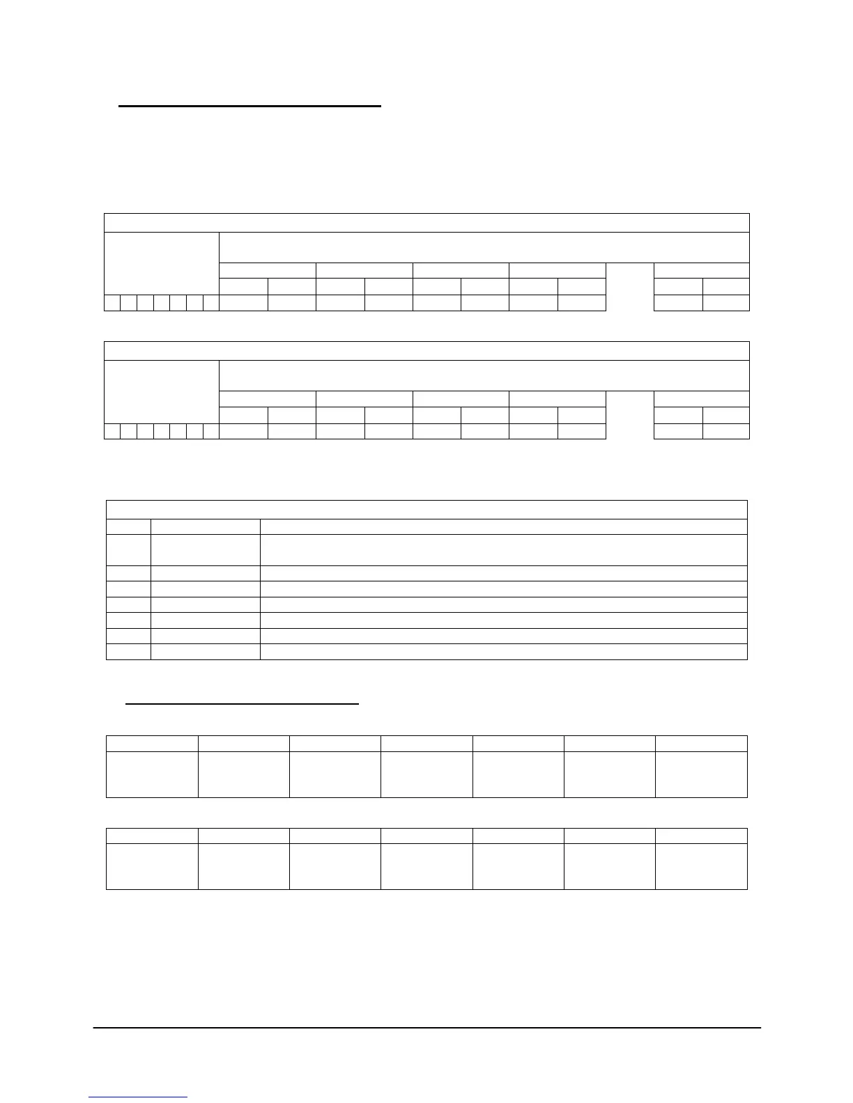
PROFIBUS Master activates the “DATA EXCHANGE” protocol in which it cyclically transmits some bytes in output
and reads some bytes in input to the PROFIBUS Slaves.
As mentioned above, there is an area of 7 bytes defined “Parametric Data” and an area of 32 bytes defined
“Process data” both in output and in input.
(from PROFIBUS Master to Slave)
“REQUEST” WORD 1 WORD 2 WORD 3 WORD 4 WORD 16
MSB LSB MSB LSB MSB LSB MSB LSB
≈
MSB LSB
1
8 9 10 11 12 13 14 15 38 39
(from PROFIBUS Slave to Master)
“REPLY” WORD 1 WORD 2 WORD 3 WORD 4 WORD 16
MSB LSB MSB LSB MSB LSB MSB LSB
≈
MSB LSB
1
8 9 10 11 12 13 14 15 38 39
“Parametric data” are “consistent” data that let you read or write any MODBUS variable, in both bit format and in
word format, in the 2400/2500 instruments connected to the PROFIBUS node.
1 TRG TRIGGER BYTE: must be incremented by 1 at each new Request.
The Reply is correct only when the value is the same.
2 ADD SLAVE MODBUS address of 2400/2500 instrument (default = 1)
3 FC Function code to specify process: Bit/Word Read/Write
4 DATUM 1 Depends on FUNCTION CODE
5 DATUM 2 Depends on FUNCTION CODE
6 DATUM 3 Depends on FUNCTION CODE
7 DATUM 4 Depends on FUNCTION CODE
4.5.1 PARAMETRIC DATA: READING A BIT
Request bytes
Trigger Slave
Address
1 or 2 Address Bit to
read
Address Bit to
read
Number of bit
to read.
(always 00)
Number of bit
to read.
(always 01)
Reply bytes
Reply to set
trigger
Confirm Slave
address
Confirm
process code.
(1 or 2)
Number of
bytes read
(always 1)
Value of bit:

 Loading...


