Use wires
of adequate
diameter
(min. 1mm
2
)
PT100,
JPT100, PTC
• Pt100 3-wires
3
1
2
“Raise” and “Lower” key
Press to increment (decrement) any numerical parameter •• Increment (decrement) speed is proportional to time
key stays pressed •• The operation is not cyclic: once the maximum (minimum) value of a field is reached, the
value will not change even if the key remains pressed.
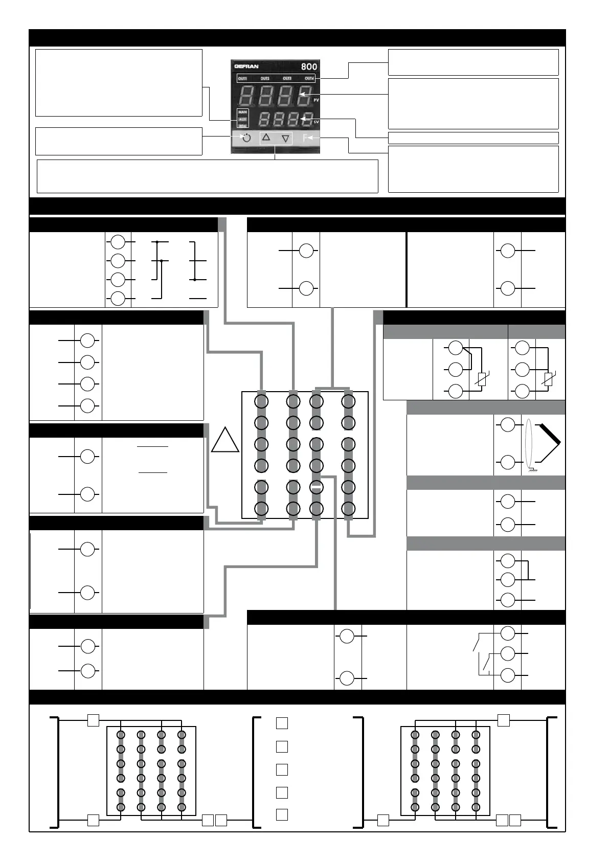
3 • DESCRIPTION OF FACEPLATE
Automatic/Manual adjustment selection
Active only when PV display visualises the process
variable
PV Display: Indication of process variable
Error Indication: LO, HI, Sbr, Err
LO= the value of process variable is < di LO_S
HI= the value of process variable is > di HI_S
Sbr= faulty sensor or input values higher than max. limits
Err= PT100 third wire opened for PT100, PTC or input
values lower than min. limits (i.e.: TC wrong connection)
Function key
Gives access to the various configuration phases ••
Confirms change of set parameters and browses next or
previous parameter (if Auto/Man key is pressed)
Function indicators
Indicates modes of operation
MAN = OFF (Automatic control)
MAN = ON (Manual control)
AUX = OFF (IN1 = OFF - local Setpoint 1)
AUX = ON (IN1 = ON – local Setpoint 2)
REM = OFF (local Setpoint)
REM = ON (remote Setpoint)
SV display: Indication of setpoint
Indication of output states
OUT 1 (Main); OUT 2 (AL 1);
OUT 3 (AL 2); OUT 4 (HB)
User configurable
generic output
- 5A/250Vac relay, cosj=1
- 11Vdc logic,
Rout = 220Ω (6V/20mA)
Configurable serial
line isolated to 1500V
Passive current loop
(max. 1200 baud)
RS422/485 or RS232
(optional)
Standard:
100...240Vac/Vdc
Optional:
20...27Vac/Vdc
50/60Hz
Digital input
isolated to 1500V
- NPN 24V, 4.5mA
- PNP 24V, 3.6mA
(12V, 3.6mA)
Linear input in dc current
0...20mA, 4...20mA
• Digital inputs / Out 5
4 • CONNECTIONS
• Outputs
+
-
User configurable generic
output
- 5A/250Vac relay, cosj = 1
- 11Vdc logic, Rout = 220Ω
(6V/20mA)
• Serial line
Available thermocouples:
J, K, R, S, T, B, E, N,
Ni-Ni18Mo, L NiCr-CuNi
- Observe polarities
- For extensions, use the
correct compensating cable
for the type of TC used
18
17
16
15
-
+
-
+
Tx
Rx
• TC
6
5
4
3
2
1
7
8
9
10
11
12
18
17
16
15
14
13
19
20
21
22
23
24
2
1
Linear input in dc voltage
0...50mV, 10...50mV,
0...10V, 2...10V
2
1
+
-
• Linear (I)
4
1
2
-
+
9
11
10
19
21
20
22
-
+
Out2 (AL1)
-
+
Out1 (Main)
IN1
IN2
COM
• Power Supply
Transmitter supply isolated
1500V
10/24Vdc, max. 30mA
short-circuit protection
23
24
~
~
• Transmitter supply
11
12
GND
+Vt
Auxiliary input isolated
1500V
Current transformer
50mAac, 1,5Ω, 50/60Hz
Remote setpoint
0...20, 4...20mA, 5Ω
0...1V, 0...10V, > 1MΩ
• Auxiliary input
14
13
~
~
• Output
User configurable
generic output
- 5A/250Vac relay, cosj=1
- 11Vdc logic,
Rout = 220Ω (6V/20mA)
- analogue output
isolated to 1500V
(0...10V, 0...20/4...20mA)
6
5
+
-
Out3 (AL2)
7
8
+
-
Out4 (AL3/
HB)
(W1)
Out 5 analogue (W2)
(alternative to IN2
digital input)
(*) terminal 11 if Out 4 is
Relay or Logic
9
7
+
COM
(IN2 alternative Out 5)
TOP
5 • RECOMMENDED WIRING LAYOUT
A
B
C
D
Inputs
Serial
Relay outputs
Power supply
AD B
Low level signals
Line voltage and outputs
A
E
D B
Low level signalsLine voltage
E
Logic/Analogue
outputs
C
Cable Channel
Cable Channel
Cable Channel
Cable Channel
-
+
(*)
PWR
!
A (Data +)
B (Data -)
RS485 2-wires
• Pt100 2-wires or PTC
3
1
2
• Inputs
TT
GND
RS232
Tx
Rx
• Linear (V)
2
80225E_MHW_800_04-2013_ENG

 Loading...


