of.52
lo.52
flt.2
ofst
tyP.2
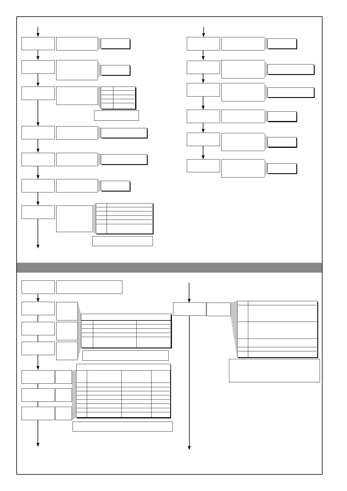
Digital filter on main input
Digital filter on display
process variable: acts as
hysteresis
Decimal point position for
main input scale, alarm
and remote setpoint
(*) not available for TC,
RTD and PTC scales
Minimum limit of main
input scale
Maximum limit of main
input scale
Offset correction
of main input
Digital filter on aux input
(if enabled)
[see “hrd.1” on Hrd]
Aux analogue input
function (if enabled)
[see “hrd.1” on Hrd]
and enable custom
limitation
Minimum range for aux
input (if enabled)
[see “hrd.1” on Hrd]
Maximum range for aux
input (if enabled)
[see “hrd.1” on Hrd]
Offset correction of aux
input (if enabled)
[see “hrd.1” on Hrd]
Lower limit for local
setpoint and absolute
alarms
Upper limit for local
setpoint and absolute
alarms
+ 8 to select custom linearization
(see table 32 values in Lin)
46
47
48
49
50
51
52
53
54
55
56
57
58
0.0 ... 20.0 sec
0 ... 9.9
scale points
dP_S Format
0 xxxx
1 xxx.x
2 xx.xx (*)
3 x.xxx (*)
min...max input range
selected in tyPE
min...max input range
selected in tyPE
-999 ... 999
scale points
tYP.2 Auxiliary input function
0 None
1 Remote setpoint
2 Analogue remote manual
3 Analogue power reset
4 Current transformer
input for HB
0.0 ... 20.0 sec
Min…max input range
selected in tyP.2
Min…max input range
selected in tyP.2
-999 ... 999
scale points
Lo.S ... Hi.S
Lo.S ... Hi.S
• Out
61
Out
Output settings
Select
reference
signal for
alarm 1
AL.1.r, AL.2.r, AL.3.r
Select
reference
signal for
alarm 2
Select
reference
signal for
alarm 3
60
62
AL.x.r Variable to compare Alarm setpoint
0 PV (Process variable) AL
1 InP.2 (aux input) AL
2 SSP (active setpoint) AL (only absolute)
3 PV (Process variable) InP.2
(aux input)
64
63
Alarm
type 1
Alarm
type 2
Alarm
type 3
+ 8 to disable on power up until first interception
+ 16 to latch alarm
65
AL.x.t Direct (high limit) Absolute Normal
Inverse (low limit) or relative
Symmetrical
to active setpoint (window)
0 direct absolute normal
1 inverse absolute normal
2 direct relative normal
3 inverse relative normal
4 direct absolute
symmetrical
5 inverse absolute
symmetrical
6 direct relative
symmetrical
7 inverse relative
symmetrical
AL.1.t, AL.2.t, AL.3.t
HB alarm
function
66
Hb_F Function description
0 Relay, logic output: alarm active
on load current level lower than
setpoint during the ON time
of the control output
1 Relay, logic output: alarm active
on load current level higher than
setpoint during the OFF time
of the control output
2 Alarm active if one of functions 0 and 1
is true (OR logic between 0 and 1) (*)
3 For continuous heating output
7 For continuous cooling output
+ 0 assigned to output Out1 (only for Hb_F= 0, 1, 2)
+ 4 assigned to output Out2 (only for Hb_F= 0, 1, 2)
+ 8 assigned to output Out3 (only for Hb_F= 0, 1, 2)
+ 12 assigned to output Out4 (only for Hb_F= 0, 1, 2)
+ 16 inverse HB alarm
(*) minimum setting is fixed at 12% of amperometric full scale
al.1.r
al.2.r
al.3.r
al.1.t
al.2.t
al.3.t
+ 4 only for relative alarms, they refer to SP1
(available if multiset function enabled)
filt
dp s
-
fild
lo s
-
xi s
-
lo l
-
xi l
-
xi.52
xb f
-
6
80225E_MHW_800_04-2013_ENG

 Loading...


