(trl
sens
al.nr
hrd.1
hrd.2
• Hrd
Hrd
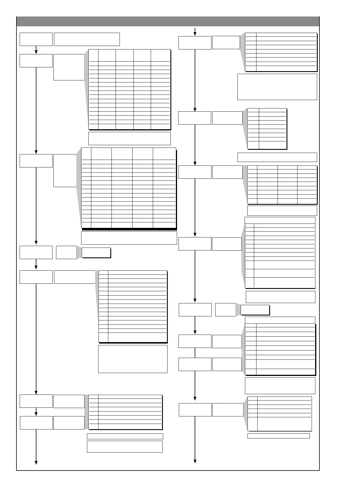
Hardware configuration
Auxiliary input
installation, digital
inputs, serial
interface.
Timer and multiset
enabling
Installation
of relay,
logic outputs
MAIN, AL1,
AL2, AL3,
and analogue
outputs W1,
W2
+ 16 to enable analogue output W1
+ 32 to enable analogue output W2
+ 64 to invert state of LEDs compared to state of output
+ 8 to enable HB alarm
+ 16 to enable LBA alarm
d.i.F.1, d.i.F.2
Function of digital
input 1 (IN1)
+ 16 for inverse logic input
+ 32 to force logic state 0 (OFF)
+ 48 to force logic state 1 (ON)
Function of digital
input 2 (IN2)
hrd.1 Aux Logic Logic Serial
analogue input 1 input 2 interface
input (IN1) (IN2)
0
1 x
2 x
3 x x
4 x
5 x x
6 x x
7 x x x
8 x
9 x x
10 x x
11 x x x
12 x x
13 x x x
14 x x x
15 x x x x
hrd.2 OUT 1 OUT 2 OUT 3 OUT 4
(relay, logic) (relay, logic) (relay, logic) (relay, logic)
0
1 x
2 x
3 x x
4 x
5 x x
6 x x
7 x x x
8 x
9 x x
10 x x
11 x x x
12 x x
13 x x x
14 x x x
15 x x x x
SnS.2 Signal
0 0 ... 1V
1 0.2 ... 1V
2 0 ... 10V
3 2 ... 10V
4 0 ... 20mA
5 4 ... 20mA
6 Potentiometer
7 CT 50mA
~
AL.nr Alarm 1 Alarm 2 Alarm 3
0 disabled disabled disabled
1 enabled disabled disabled
2 disabled enabled disabled
3 enabled enabled disabled
4 disabled disabled enabled
5 enabled disabled enabled
6 disabled enabled enabled
7 enabled enabled enabled
0 No function (disabled input.)
1 MAN / AUTO controller
2 LOC / REM
3 HOLD
4 Start / Stop timer
5 Reset timer
6 Software on/off
7 Alarms memory reset
8
SP1...SP2 (2SP) Selection
SP1...SP4 – bit Lo Selection
9 SP1...SP4 – bit Hi Selection
Selection of probe
type for aux input
Select number of
enabled alarms
+16 to enable the Timer function
+32 to enable the Multiset function (2SP)
+64 to enable the Multiset function (4SP)
Start / Stop Timer
0 from enabled digital input
1 from AL1 ON
2 from AL2 ON
3 from AL3 ON
4 from ALHB ON
5 from serial line (address 0049H, bit 0)
6 from serial line (address 0049H, bit 1)
7 from keys
Reset Timer
(0 ... 15)
+ 8 to enable main input curve 4 point correction
(alternative to custom linearization).
See description in “Main Input Correction
Function” section.
+16 to disable averaging filter on sampled
value (available from software release 3.05)
+8 to disable averaging filter on sampled value
(available from software release 3.05)
SEnS Probe type for main input
0 Thermocouple (TC)
1 Resistance Thermometer (RTD)
2 Thermistor (PTC)
3 Voltage 0...50mV / 10...50mV
4 Current 0...20mA / 4...20mA
5 Voltage 0...10V / 2...10V
6 Custom 10V
7 Custom max 50mV
Selection of
probe type for
main input
Control type
[0...78]
43
CtrL Control type
0 P heat
1 P cool
2 P heat / cool
3 PI heat
4 PI cool
5 PI heat / cool
6 PID heat
7 PID cool
8 PID heat / cool
9 ON-OFF heat
10 ON-OFF cool
11 ON-OFF heat / cool
12 PID heat + ON-OFF cool
13 ON-OFF heat + PID cool
14 PID heat + cool with relative gain
(see C.MEd parameter)
0 No function (key disabled)
1 MAN / AUTO controller
2 LOC / REM
3 HOLD
4 Start / Stop selftuning
5 Start / Stop autotuning
6 Set / Reset outputs Out 1... Out 4
7 Alarms memory reset
8 SP1 / SP2 Selection
9 Integral contribution instantaneous
zero setting
10 Start / Stop Timer
(se S.S.t. = 7)
11 Reset Timer
(se _rt = 7)
+16 Autoreset enabled (Stop = program reset)
(only for _S.S.t. parameter)
+8 inverse action
+16 disable function in configuration menu
Selection of derivative action
sampling time:
+ 0 sample 1 sec.
+ 16 sample 2 sec.
+ 32 sample 8 sec.
+ 64 sample 240 msec.
b u t t
Function of M/A
keys: “*”
Defining SV
display function
diSP Lower display (SV) function
(*) 0 SSP - setpoint enabled
(*) 1 InP.2 - aux input
(*) 2 Control output value
(*) 3 Deviation (SSP - PV)
8 Visualisation of current time on PV
display and tS time on SV
display
(*) + 4 Timer in start
Note: scale selection with “tYPE” code in InP
Note: LbA alarm is not enabled with ON/
OFF type control
sns.2
s.S.t.
-
r.t.
--
disp
d.i.f.2
d.i.f.1
butt
hrd.3
0
Non significant
function
but.2
0
Non significant
function
8
80225E_MHW_800_04-2013_ENG

 Loading...


