5.2.5.6 Power supply unit R-SM3-ADV regulation card (only for sizes ≥ 71600) for drive S/N previous than S/N:
34GG044151
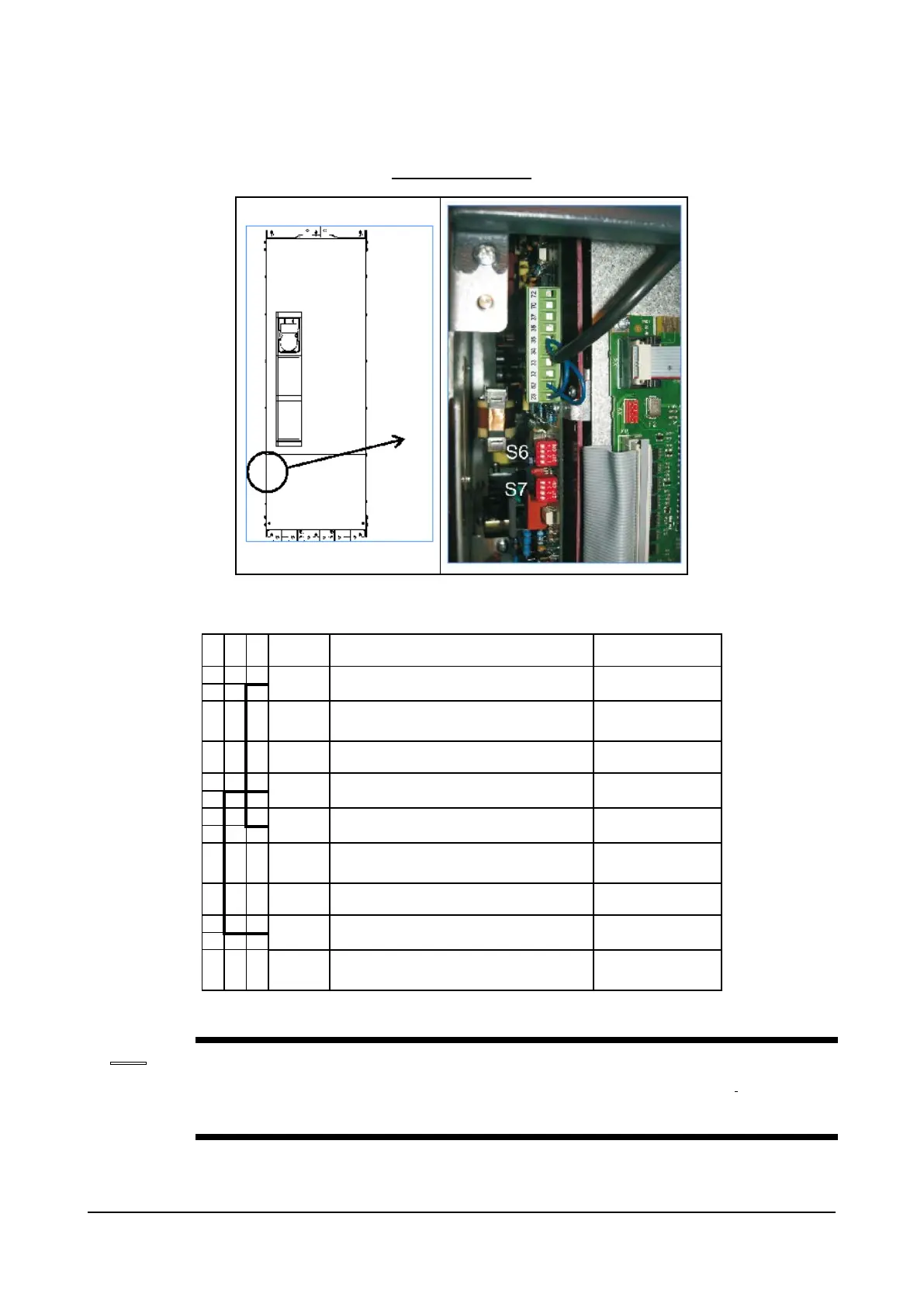
Figure 1: Terminals location
Terminals Function Voltage / Current
23 Input of the pre-charge enable control (15 - 35V, 5 - 11mA)
32 Output of the MLP static signal (low - active signal)
source)
33 (Common) Ground of the MLP and ML static signals -
34 Reference point for Power supply +24V -
35 Power supply output +24V (32V / 300mA max)
36 Output of the ML signal (low - active signal)
sink)
37 Power supply of the ML and MLP signals (35V max)
52 (Common) Ground of the pre-charge enable control -
70, 72 OK Relay
AC11)
The jumpers shown are factory-wired.
Wiring of the OK relay contact (70 - 72) in series with the Enable chain of the ADV200 regulation card
is recommended.
Addendum to the ADV200 / ADV200WA QS Instruction books Page 10 of 20
 Loading...


